Congrats on a very impressive review.
Review and Measurements of Okto DAC8 8Ch DAC & Amp | Audio Science Review (ASR) Forum
Review and Measurements of Okto DAC8 8Ch DAC & Amp | Audio Science Review (ASR) Forum
Hello.
Just making shure about i2s connections and stuff")
Data 1-4, done.
mclk to Pulsar clock. Still waiting for the regulator so....
Solderpad to be shorted is jp1 ?
bclk to usb reciver, done.
That schould be it, right ?
If more gain is needed do you have a table for what resistance gives what result ?
The resitors in question have to be the 1k ones, right ?
Just making shure about i2s connections and stuff
Data 1-4, done.
mclk to Pulsar clock. Still waiting for the regulator so....
Solderpad to be shorted is jp1 ?
bclk to usb reciver, done.
That schould be it, right ?
If more gain is needed do you have a table for what resistance gives what result ?
The resitors in question have to be the 1k ones, right ?
Lets say that I would like twice the amount of gain on two channels ( I have
dipole subs that need some serious compensation) what would be the value of
these resistors ?
Are channel 1-2 the ones located closest to the the back of the board ?
To enter ON: I should short gpio1 to ground, right ?
dipole subs that need some serious compensation) what would be the value of
these resistors ?
Are channel 1-2 the ones located closest to the the back of the board ?
To enter ON: I should short gpio1 to ground, right ?
Last edited:
There is a discrepancy in the manual at page 5 and 8 regarding the 15v connections. Could be confusing even though I belive that page 5 would be correct.
Thanks for pointing that out. Page 5 is correct and page 8 wrong. We're going to fix that.
Lets say that I would like twice the amount of gain on two channels ( I have dipole subs that need some serious compensation) what would be the value of these resistors ?
2k (or closest value you can get)
Closest to the data connector.Are channel 1-2 the ones located closest to the the back of the board ?
Actually, newest firmware revision does that through the onboard MCU. Thus there is no need to have the jumper in place, while the signal from the MCU can be overridden. We also have to update the manual on that point.To enter ON: I should short gpio1 to ground, right ?
Pavel
Actually, newest firmware revision does that through the onboard MCU. Thus there is no need to have the jumper in place, while the signal from the MCU can be overridden. We also have to update the manual on that point.
Pavel
So when will the "pwr" led be lit, all voltages are in place ? (no jumper yet) (clock still the onboard one)
Last edited:
GPIO1 ON/STANDBY:
When pulled high, DAC8 enters active state if all power supplies are at nominal levels.
Maximum voltage on this pin is 3.3V, use jumper to short this pin high if not in use.
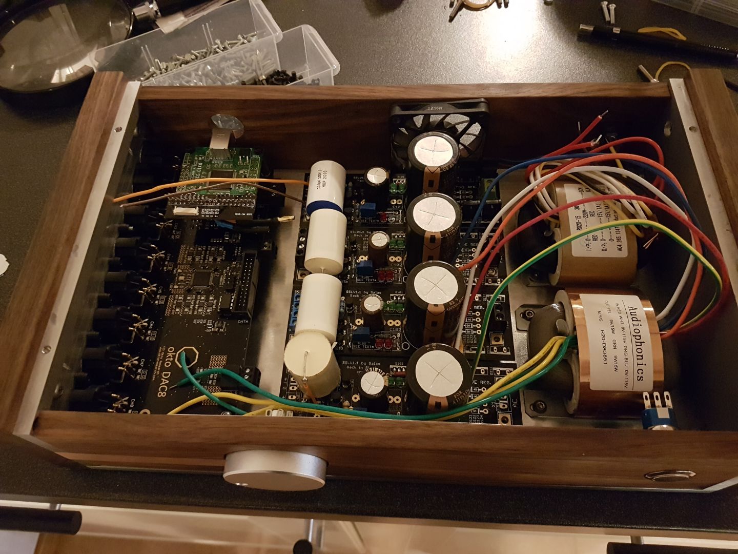
On this Picture you can see a jumper between pin1 (3.3V) and pin3 (GPIO1).
Is this what's ment with the text above ?

I'm using the possibility with the Sabre volumecontrol as descibed in the connection diagram.
Last edited:
The board looks really nice and the build is coming along
Any updates on your progress ???

- Status
- Not open for further replies.
- Home
- Vendor's Bazaar
- Okto Research modules