Yes, it was never intended to work with both sockets connected to cables.
Yeah, but somebody will do it. Especially in a preamp or headphone amp. The use case for a power amp is much simpler. Neat trick regardless.
And the input circuit of the Self preamp in Linear Audio doesn't even have these resistors, IIRC.
Yeah. The 100 Ω shown in the power amp book isn't technically needed.
Tom
Yeah. The 100 Ω shown in the power amp book isn't technically needed.
What I'm wondering about is: are these resistors (let's just say the pair of high value resistors for the XLR input) needed before the relays of the input selector board, or can they be omitted from there and the preamp (or other differential input circuit) be given the responsibility to do whatever is needed?
If you're taking Doug Self's circuit from fig. 20.5 in the power amp book, I'd probably do the switching after the two 10 kΩ input resistors, but you could just as well switch just after the input connectors. Do check the chapter on signal switching in his Small Signal Audio book if you want the switching accomplished cleanly.
I don't like the highish impedances of Self's input. 10 kΩ adds a lot of noise. So I tend to use an instrumentation amp input. It costs an extra (dual) opamp, but gives you very high input impedance. This makes life easier for the RF input filter and allows me to set the input impedance to whatever I want. With the IA input, I'd just switch the two input signals between XLR and RCA. Just keep in mind that you need to control the common-mode voltage if you sense the RCA differentially.
Tom
Thanks. Will think and read more, and come back.Just keep in mind that you need to control the common-mode voltage if you sense the RCA differentially.
Now about caps for the Modulus-686.
I was thinking of these options:
- Find Electronic Components | Mouser United Kingdom OR
- Find Electronic Components | Mouser United Kingdom
I was thinking of putting two of these on each rail, to give me 30,000uF per rail. Is that a good amount? I was just going by the formula of "100uF per rail for each Watt of rated output".
In the Power-686, you're doing 50V caps. Do you feel there's any point in the additional safety margin of 63V? And you're doing 44,000uF capacitance against the 30,000uF I was planning on. Is my reduction in capacitance acceptable, if I mostly operate the amp on 8 Ohmish loads and at "domestic" power levels?
Last edited:
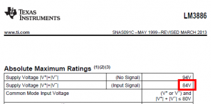
Since you are not allowed to apply more than ±42 volts to the LM3886, you need to design and build a power supply which never exceeds that. Even when playing very softly, where the amp is only delivering 1 milliwatt to the loudspeakers. Even when the mains AC voltage is at its highest possible value (+7% in US, more in India, I am told). So if you think 50 volt capacitors are safe for <42 volt supplies, use those. If you feel you really truly need 63 volt capacitors to be double extra safe and sure with <42 volt supplies, use those.
_
_
Attachments
Last edited:
If you feel you really truly need 63 volt capacitors to be double extra safe and sure with <42 volt supplies, use those.
Understood. You're saying it's my call. Fair enough.
What about the 85C vs 105C? And what is the total capacitance needed for full power but not into difficult 2 Ohm loads?
85 vs 105 ºC affects reliability. The 105 ºC rated caps will last longer (assuming all other variables are held constant). Be careful when comparing the specs, though. A cap rated for 10000 hours at 85 ºC may outlast a cap rated for 1000 hours at 105 ºC. The lifetime vs temperature function is not linear! If you're truly concerned about this, I suggest contacting the manufacturer of the capacitors.
Many use 10000 uF (10 mF) per 100 W (8 Ω) as a guideline. So 22000 uF per rail would be appropriate (says this guideline). I'd double that.
Note that the MOD686 is not rated for 2 Ω operation. It's stable there and I have even driven a 1 Ω load with the MOD686 by accident at one point. No ill effects observed, but I would not recommend making that the typical operating point.
Tom
I have a question about this part: MegaFit pre-crimped lead, 16 AWG, 30 cm, Molex part number 68801-4955, Mouser part number 538-68801-4955.
This item is not available, so I switched to the 12 AWG variant, which is in stock. So far so good.
Then I thought I'll pick up some loose crimp terminals without wires, so that I can crimp wires as needed. The power leads will definitely fit in 30cm, but the leads to the speaker terminals may fall short. So, I started looking for just the loose crimp terminals.
Am I right that I should look for the female crimp terminals, not the male ones? If yes, I found these
I believe the pre-crimped wire leads the BoM prescribes use the gold contact terminals, right? So, I should get the same, if I'm getting loose terminals?
One strange thing is that the pre-crimped terminals with wire leads costs $0.79 each, whereas loose crimp terminals cost $1.12 each, for the same quantities. Am I comparing apples to apples, or should I be looking at some other loose terminal variant?
This item is not available, so I switched to the 12 AWG variant, which is in stock. So far so good.
Then I thought I'll pick up some loose crimp terminals without wires, so that I can crimp wires as needed. The power leads will definitely fit in 30cm, but the leads to the speaker terminals may fall short. So, I started looking for just the loose crimp terminals.
Am I right that I should look for the female crimp terminals, not the male ones? If yes, I found these
- Loose crimp terminals: female: 12 AWG -- tin contacts -- $0.28
- Loose crimp terminals: female: 12 AWG -- gold contacts -- $1.28
I believe the pre-crimped wire leads the BoM prescribes use the gold contact terminals, right? So, I should get the same, if I'm getting loose terminals?
One strange thing is that the pre-crimped terminals with wire leads costs $0.79 each, whereas loose crimp terminals cost $1.12 each, for the same quantities. Am I comparing apples to apples, or should I be looking at some other loose terminal variant?
Last edited:
Your links didn't work, so I dug out the part numbers:
538-172063-0311-LP for 14-16 AWG.
538-172063-0312-LP for 12 AWG.
The crimped leads are standard Molex products. I don't think the loose terminals are. Usually they come on a strip. Maybe Mouser charges extra to remove them from the strip. This allows you to buy one terminal instead of having to buy a strip of 100.
One approach would be to get the pre-crimped leads and just extend them. Cut, strip, solder. heat shrink. I generally prefer a contiguous run, though. Then again, Molex does a better job at crimping the terminals than I can do. Tradeoffs, tradeoffs.
Tom
Yes, you're right! So sorry...Your links didn't work,
Maybe.The crimped leads are standard Molex products. I don't think the loose terminals are. Usually they come on a strip. Maybe Mouser charges extra to remove them from the strip. This allows you to buy one terminal instead of having to buy a strip of 100.
Isn't it a bad idea to splice high current wires? I used to somehow assume that this was one of the Bad Things To Do, without thinking too much about why. The only splicing I used to be told was acceptable was if one crimps both sides using one of those thin copper tube-like sleeves, then heat-shrinks to cover it all.One approach would be to get the pre-crimped leads and just extend them. Cut, strip, solder. heat shrink. I generally prefer a contiguous run, though.
Anyway.... I'll get myself a few loose terminals and play with them. One last question: is gold necessary for high current connectors like this? Isn't the tinned alternative good enough? I used to believe gold makes a big difference for really low voltage connections and contacts because it keeps the corrosion away, which keeps the contacts healthy in the absence of much potential difference.
Isn't it a bad idea to splice high current wires?
Which is worse:
- A bad crimp termination at the end of a contiguous piece of wire.
- A solder splice in the middle of a wire with good end terminations.
One last question: is gold necessary for high current connectors like this?
It wouldn't hurt anything (other than your wallet). It may save you from corrosion, though, unless you live in a humid environment, that's not likely to be an issue. I've used the tin plated connectors. They've performed well for me.
Tom
Ok, ok.... I hear you both.  I'll get the gold plated terminals. They're FIVE times as expensive. But then they feed into the Modulus 686, which is twenty times as expensive as a 150W amp kit from Shenzhen, so....
But I am a man of principles. I won't splice high current wires. I will buy a few extra tin plated terminal and practise crimping them, and I'll then make my own 60cm long leads with the gold plated terminals. Otherwise what will happen to the plumpness of the strings of the double bass, the silkiness of the female vocals, the holographic soundstage which extends two blocks of buildings on either side of my living room, and the alignment of the cryo crystals in my earlobes and the tingling of my extremities? If I don't care about all this, I might as well buy a Pioneer or Marantz amp.
Jokes apart, I live in an area where humidity is not a joke. It is one of the largest metropolises of the world, but (a few) people literally die here in accidents, wall collapses, every year due to torrential rains which last a few months. Tragic and unbelievable, but true. You ain't seen no humidity yet till you've lived a few monsoons in Bombay. This year, daily peak rainfall on a few of the days in Bombay exceeded peaks of Cherrapunji, the town we have all read about as having the highest recorded rainfall in the world.
I'll get the gold plated terminals. They're FIVE times as expensive. But then they feed into the Modulus 686, which is twenty times as expensive as a 150W amp kit from Shenzhen, so.... But I am a man of principles. I won't splice high current wires. I will buy a few extra tin plated terminal and practise crimping them, and I'll then make my own 60cm long leads with the gold plated terminals. Otherwise what will happen to the plumpness of the strings of the double bass, the silkiness of the female vocals, the holographic soundstage which extends two blocks of buildings on either side of my living room, and the alignment of the cryo crystals in my earlobes and the tingling of my extremities? If I don't care about all this, I might as well buy a Pioneer or Marantz amp.
Jokes apart, I live in an area where humidity is not a joke. It is one of the largest metropolises of the world, but (a few) people literally die here in accidents, wall collapses, every year due to torrential rains which last a few months. Tragic and unbelievable, but true. You ain't seen no humidity yet till you've lived a few monsoons in Bombay. This year, daily peak rainfall on a few of the days in Bombay exceeded peaks of Cherrapunji, the town we have all read about as having the highest recorded rainfall in the world.
Last edited:
So, the next question is: what's the contact material inside the PCB mounted sockets in this case?Looks like I mis-typed -- fingers not knowing what the brain was thinking. I meant to say that the experts considered Sn-to-Sn is better than mating different materials such as Au-to-Sn.
Actually, the discussion in my previous life came about when the wise ones were replacing IC sockets containing Au-plated pins with sockets that had tin-plating as semiconductor companies had long before abandoned doing commercial IC products with gold-plated leads.
One needs to keep in mind that this was in a business that made products that would perform for many years in harsh environments. It is probably not of concern with domestic audio applications. More important is that the mating pieces make 'gas-tight' connections to each other. Tom specifies good sockets, so most of this discussion is hypothetical. Note also that if you are going to put your DIP ICs in sockets, it is good to get sockets with machined pins rather than the cheaper styles as these do a better job of grabbing the IC pins for a gas-tight connection.
One needs to keep in mind that this was in a business that made products that would perform for many years in harsh environments. It is probably not of concern with domestic audio applications. More important is that the mating pieces make 'gas-tight' connections to each other. Tom specifies good sockets, so most of this discussion is hypothetical. Note also that if you are going to put your DIP ICs in sockets, it is good to get sockets with machined pins rather than the cheaper styles as these do a better job of grabbing the IC pins for a gas-tight connection.
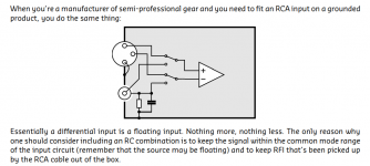
Pretty exciting -- @alexcp pointed me to a PDF published by the Hypex designer about grounding, and it has this diagram about connecting an RCA and an XLR in parallel. It uses a switch, however, which is more complex than I wanted to do.Yes, it was never intended to work with both sockets connected to cables.
And the input circuit of the Self preamp in Linear Audio doesn't even have these resistors, IIRC.
My quest to figure out the perfect but simple way to have an input support both XLR and RCA continues...
Attachments
XLR+TRS doesn't solve my problem. Both XLR and TRS are balanced. I want balanced and unbalanced.Couldn’t you use a combo connector which has XLR and TRS on the same connector?
At least in an industrial setting, you generally wouldn't be allowed to splice in the middle of a wire run, whether to meet client spec or electrical code. Of course, an amp hardly has walls that prevent viewing the entirety of the wiring.Which is worse:
That's the question. Now, maybe "bad" isn't the right word here, but I hope you get what I mean. Without the proper crimp tool (and the correct die) you will not get good crimp. So you end up doing your best and soldering the wires to the crimp contacts. Is that better than soldering the wire in the middle? I doubt it. But that's my opinion. I haven't measured the difference - and doubt I can.
- A bad crimp termination at the end of a contiguous piece of wire.
- A solder splice in the middle of a wire with good end terminations.
It wouldn't hurt anything (other than your wallet). It may save you from corrosion, though, unless you live in a humid environment, that's not likely to be an issue. I've used the tin plated connectors. They've performed well for me.
Tom
As for soldering to the crimp connector, I think you avoid the oft-mentioned fatigue issue as long as the solder stays on the "downstream side" (i.e. the free end of the conductor) and kept away from where the conductor is actually crimped.
- Home
- Vendor's Bazaar
- Modulus-686: 380W (4Ω); 220W (8Ω) Balanced Composite Power Amp with extremely low THD