Really great built Matt! Now you have a powerhouse that sounds just as good at max RMS wattage as well as the all important 1st watt.
Enjoy...looking forward to the new SMD 186/286 designs that are coming around the corner...
Of note, one of my colleagues prefers the 686 to the ICEEDGE 1200AS. That’s a great achievement!
Best,
Anand.
Enjoy...looking forward to the new SMD 186/286 designs that are coming around the corner...
Of note, one of my colleagues prefers the 686 to the ICEEDGE 1200AS. That’s a great achievement!
Best,
Anand.
Of note, one of my colleagues prefers the 686 to the ICEEDGE 1200AS. That’s a great achievement!
That's cool!
Tom
Just a heads up: Once the current stack of boards have sold, I will stop offering the SMD pre-populated board option. At that time, the price the fully assembled module will increase to $549.
I also expect to have 20 fully assembled boards in stock by the end of the month. I will use the SMD pre-populated boards as the starting point and assemble the remaining components by hand.
By focusing on the fully built modules, I can deliver a better product and a better build experience at a very reasonable price point.
If you would like to take advantage of the lower pricing, you can order your boards here: Modulus-686
The fully assembled modules are available on backorder. I expect to be able to fill the backorders by November 1st. If you'd like to be early in line, I suggest placing your backorder now.
Tom
Thanks, now I just have to decide which way to go with the amp for the lx-minis. I am leaning towards the Mod686/Mod186 pairing with a 22VAC transformer. It should work in 3Ux300 enclosure. It would allow me to use my existing Mod86 amp until I get around to getting the Mod186 boards. Would that heat sink work on a 4 ohm load or only an 8 ohm load? I guess it also depends on how hard you push it.
With 2x22 VAC, you're looking at about ±28-30 V rectified. That'll give you about 130-140 W into 8 Ω from the Modulus-686 and 40 W into 8 Ω from the Modulus-86/186/286. 200+ W into 4 Ω from the '686 and 65 W into 4 Ω from the 86/186 and pushing 80 W into 4 Ω with the MOD286. That should be plenty for the LXmini.
The 3U Dissipante chassis will be a good fit for such an amp, assuming you're planning to put the MOD686 on its own heat sink. That heat sink will work both for 4 Ω and 8 Ω loads, assuming music reproduction.
If you wanted to make the amp a dedicated LXmini amp and use the MOD686 on the 8 Ω woofer and the MOD186/286 on the 4 Ω tweeter, you could even go with a 2U Dissipante chassis, assuming the transformer will fit. That'd make a nice and compact build. The only drawback is that if you were to change speakers and need the MOD686 to drive a 4 Ω load, it would overheat if you did so at clipping levels for more than 15-20 minutes.
If you're using 2x22 VAC, you'll want a 300-400 VA transformer with a Power-686 for powering the MOD686+MOD186/286 amp.
Tom
Last edited:
Would a Power 86 work for a Mod868/Mod186 pairing or would I need to use the Power686?
If using Antek transformers, a 200VA transformer will fit in a 2U enclosure, but a 300VA will not or at least without some box modifications, so I will most likely go with a 3Ux300, but I will see if it fits in a minidisspante.
Do you see any issue with mounting the ISS below a Power-686?
If using Antek transformers, a 200VA transformer will fit in a 2U enclosure, but a 300VA will not or at least without some box modifications, so I will most likely go with a 3Ux300, but I will see if it fits in a minidisspante.
Do you see any issue with mounting the ISS below a Power-686?
The Antek AS-3222 is 70 mm tall. The 2U Dissipante has 80 mm internal height. In fact, I run the AS-3222 in a 2U eBay chassis in my 4xMOD86. The 400 VA AS-4222 is the same height.

I doubt you can squeeze the transformer into a Mini Dissipante, though. The 250 mm internal width is a killer. The 300 VA transformer is 5" in diameter. The 400 VA is 5.5". The boards are 2.45" deep, including the back plate. So (2*2.45+5.5)*25.4 = 264 mm. Maybe if you scoot the MOD186/286 towards the front panel and the transformer towards the rear. It'll be tight, but it could potentially work. I'd assemble the circuit boards and get the transformer to play with the shapes before ordering the chassis.
You'd probably be OK with the Power-86, but I think the beefier rectifier and additional supply cap is worth having for a MOD686+MOD186/286 build. I don't see any issue mounting the ISS below the Power-686.
Tom
At the very least would be the not inconsiderable additional cost of two chassis and connecting cables. Personally I like as few boxes and interconnects as possible and actually don’t mind the height of a 3U, which could make some of the shoehorn/ dental surgery tight work a bit easier.
Last edited:
Out of interest, do you have a view on whether having the power supply elements (e.g. soft start, transformer(s) and rectifier board(s)) in a separate enclosure is angood or bad thing?
He answered this months ago referring to external PSU in a Mod86, I assume Mod686 will be the same:
Yes. There are many downsides to housing the supply separately. You maximize the supply impedance that way, which is never a good idea. Also, the currents drawn by a Class AB output stage are not pretty. Each amp half draws a pulse each half of the signal cycle, so the currents are relatively high bandwidth --> good sources of EMI.
Separating the supply from the rest is sometimes done on phono amps where hum is the main concern. Even on those amps, you still have the drawback of the increased supply impedance, but at least the currents drawn by such an amp are usually pretty nice as the amp runs (mostly) in Class A and doesn't draw that much current. In phono and preamps, you could also implement local supply regulation in the amp enclosure to minimize the supply impedance.
Then again, in my DIFF PRE 8x2, I used a pair of switching power bricks for the supply and the worst case mains hum I measure on the output is -115 dBV (1.8 µV). In the HP-1 I added regulators to the switching supplies and pushed the mains hum down below -136 dBV (160 nV).
Something tells me that doubling the chassis cost by having to build two enclosures isn't necessary for good performance. One just have to pay attention to the circuit layout.
Tom
Yeah. I'm not a fan of the separate supply and umbilical cord, especially in the case of power amps. It's an EMI nightmare waiting to happen for reasons I've outlined in the quote above.
Also, many who build the amp and supply into separate enclosures choose identical enclosures and stack the amp on top of the supply. That is rather likely to make any mains hum worse, so in addition to the EMI issues and supply inductance issues, you're now also creating a hum issue.
Tom
Also, many who build the amp and supply into separate enclosures choose identical enclosures and stack the amp on top of the supply. That is rather likely to make any mains hum worse, so in addition to the EMI issues and supply inductance issues, you're now also creating a hum issue.
Tom
At the very least would be the not inconsiderable additional cost of two chassis and connecting cables. Personally I like as few boxes and interconnects as possible and actually don’t mind the height of a 3U, which could make some of the shoehorn/ dental surgery tight work a bit easier.
It's not so much of a height issue, actually. The transformer is the tall pole in the tent and will fit within the 80 mm of a 2U chassis with 10 mm to spare. The issue is the width of the Mini Dissipante. The 250 mm internal width is pretty tight.
The Dissipante (not Mini) increases this to 350 mm if I recall correctly. That's plenty of room. 2U would work under the constraints I mentioned a few posts back. Otherwise, I'd use 3U for 4 Ω operation on ±27 V rails and 4U for ±36 V rails. The 430 x 300 mm footprint of the Dissipante is a pretty common HiFi component footprint size.
Also: Don't forget that you need to allow room for the wires to exit the board. The MegaFit connectors require a good 40-50 mm of bending radius on the leads. One trick is to build your modules with the vertical connectors (file off the locating tab and triple-check that you have the orientation right).
Tom
Last edited:
Re 3U height, I was probably thinking of builds like the 686 with a pair of the Meanwell SMPS stacked vertically, or Guardians directly mounted on the rear panel for those folks still wanting to use binding posts rather than Speakons. But of course, it’s all postulation on my part until I actually build something.
Last edited:
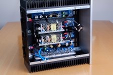
The mod686 on one heat sink, the transformer in the opposite front corner close to the opposite side heat sink, the Mod86/Mod186 on the opposite heat sink towards the middle/back, and the Power686 and ISS stacked in the center. All the boards fit in 2d cadd representations, but it doesn't include wire clearances or heights of the boards.
I have the 2U 4xMod 86 minid chasis I could use for layout purposes.
I have the 2U 4xMod 86 minid chasis I could use for layout purposes.
I considered stacking the Mean Well SMPSes as well. The cage-free version (RPS-400-27) seemingly lends itself to stacking. Unfortunately, one of the standoffs will interfere with the control connector (located on a vertically mounted sub-assembly PCB). You can kinda/sorta make it work, but I really don't like the amount of torque it puts on the sub-assembly. I also wonder how that affects airflow for the lower PCB.
That's one of the reason I spent a few bucks more (literally!) to get the caged version (RPS-400-27-C) and mounted them vertically side-by-side in the 3U Mini Dissipante.
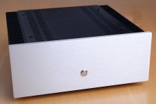
Anyone interested in building a copy of my MOD686 amp can request that exact chassis from ModuShop. The chassis will set you back about $350/each due to the amount of modification I do. I have ModuShop modify all panels except the top panel. It's a bit pricey but man it is so nice to have a chassis that just requires the turning of a screwdriver when it arrives.
If any of you is interested in going this route, please ping me and I'll send the latest CAD drawings to ModuShop.
If any of you is interested in buying one of these, also let me know. I'm thinking $3250 would be a reasonable price point for a custom built amp of this performance. Quite a few of the attendees at the Vancouver Island DIY Fest agreed with me on this.
Tom
That's one of the reason I spent a few bucks more (literally!) to get the caged version (RPS-400-27-C) and mounted them vertically side-by-side in the 3U Mini Dissipante.
Anyone interested in building a copy of my MOD686 amp can request that exact chassis from ModuShop. The chassis will set you back about $350/each due to the amount of modification I do. I have ModuShop modify all panels except the top panel. It's a bit pricey but man it is so nice to have a chassis that just requires the turning of a screwdriver when it arrives.
If any of you is interested in going this route, please ping me and I'll send the latest CAD drawings to ModuShop.
If any of you is interested in buying one of these, also let me know. I'm thinking $3250 would be a reasonable price point for a custom built amp of this performance. Quite a few of the attendees at the Vancouver Island DIY Fest agreed with me on this.
Tom
Attachments
Last edited:
The mod686 on one heat sink, the transformer in the opposite front corner close to the opposite side heat sink, the Mod86/Mod186 on the opposite heat sink towards the middle/back, and the Power686 and ISS stacked in the center. All the boards fit in 2d cadd representations, but it doesn't include wire clearances or heights of the boards.
A lot of the wiring clearance can be shifted to the space above the boards by using the vertical connectors. If you're assembling your own boards from the SMD pre-populated boards, all you have to do is to get the vertical version of the various connectors. For the Molex MegaFit, there's a locator tab that you need to remove (the compact vertical connectors were released just after the Modulus-686, so the layout does not feature the holes required for the tab). Then triple-check that you install the connectors correctly. The locking tab should face the LM3886es.
If you need me to assemble a module for you with the vertical connectors, just toss me an email. Preferably before or just as you're placing your order.
Tom
The vertical connectors seem the way to go for my build. I have two 2x22VA 200VAC transformers and two Power86's would they work on a temporary basis for a pair of Mod686/Mod86's since I already have them ") ? I would ultimately get a larger 400VA transformer and the Power686 for each amp, and reuse the Power86's and the 200VA transformers for Mod86 2 and 3 channel builds for my surround system.
? I would ultimately get a larger 400VA transformer and the Power686 for each amp, and reuse the Power86's and the 200VA transformers for Mod86 2 and 3 channel builds for my surround system.
? I would ultimately get a larger 400VA transformer and the Power686 for each amp, and reuse the Power86's and the 200VA transformers for Mod86 2 and 3 channel builds for my surround system.- Home
- Vendor's Bazaar
- Modulus-686: 380W (4Ω); 220W (8Ω) Balanced Composite Power Amp with extremely low THD