I am working on a few reference schematics. Also an article is upcoming in audioXpress. It's pretty simple.
You typically need some kind of buffer on the input to drive the grid. I have used both a JFET buffer, and a small MOSFET follower. Either works well. If the input impedance of the class D amp is low (10's of K) you also need an output buffer - same idea, JFET or MOSFET.
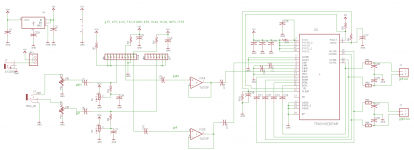
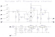
I am attaching the schematic of the entire class-D hybrid amp I built (shown below). I used dual JFETs to buffer in and out, and a JFET phase splitter to drive complementary inputs to the class D. This preformed better than driving it single-ended.
Pete
I don't understand why you need additional jfet for NuTube output. Is it that the Nutube has high impedance output or just not able to drive a reasonable load?
That said, I will be interested in an assembled buffer board for my class D amp using the tpa3250
")
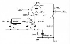
The Nutube has a plate resistance of about 330k. So the output impedance (plate resistance in parallel with plate load resistor) is typically ~100-200k ohms.
If whatever it is driving has a high input impedance, then no buffer would be needed. But to drive, say, a 10k input impedance, you would need some kind of buffer. A simple follower (JFET or MOSFET) works fine. An opamp can also be used.
Pete
If whatever it is driving has a high input impedance, then no buffer would be needed. But to drive, say, a 10k input impedance, you would need some kind of buffer. A simple follower (JFET or MOSFET) works fine. An opamp can also be used.
Pete
Useful schematics make them much more interesting.
Cheers
Cheers
Attachments
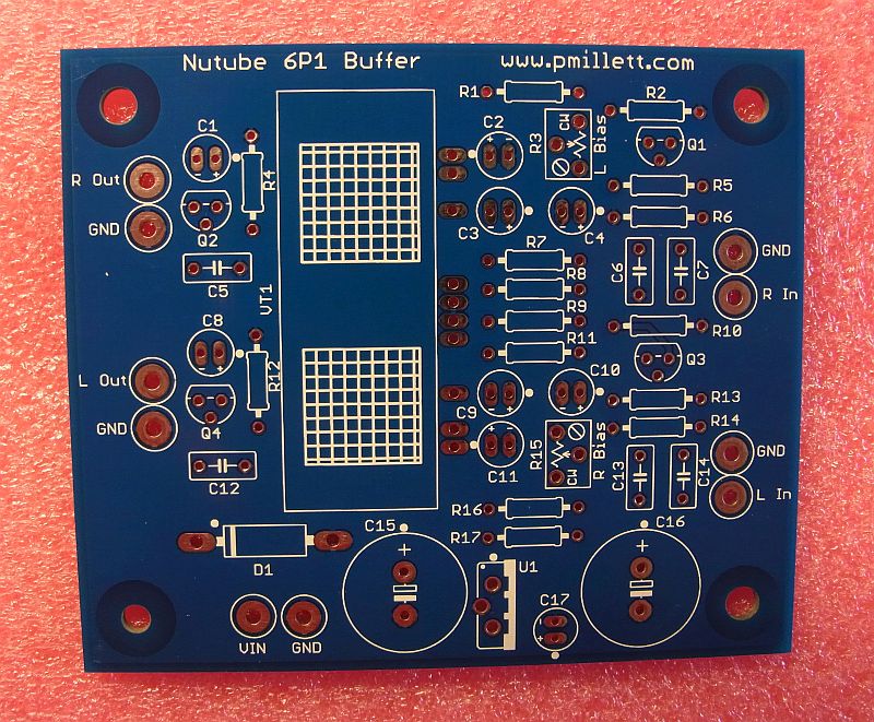
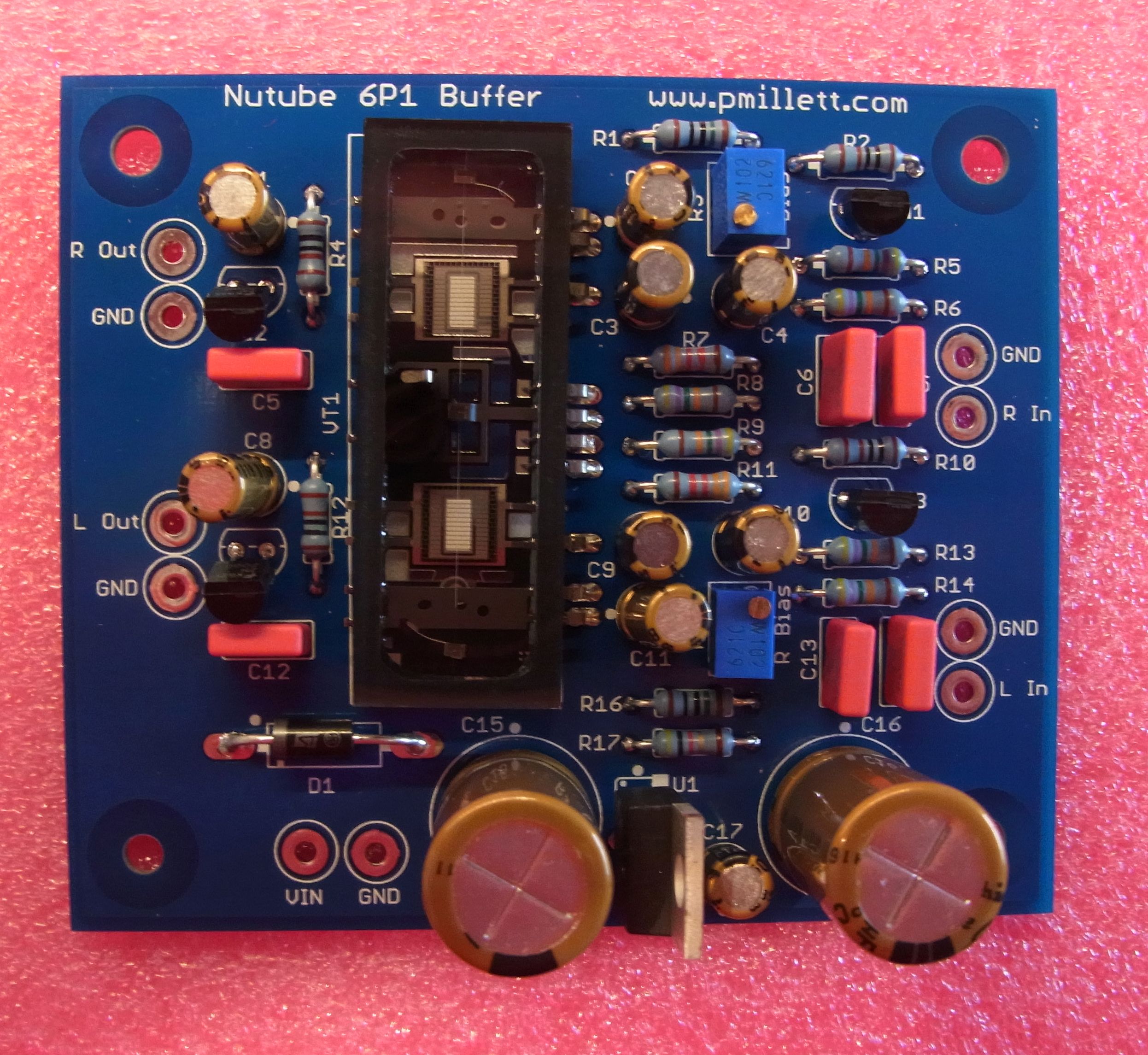
Nutube 6P1 Buffer PCB available now
I now have a simple buffer PCB available for the 6P1. You can see details here:
Nutube 6P1 Buffer PCB.
I sell a blank PCB and the Nutube together - you need to buy the rest of the parts from Mouser and assemble it yourself. They are available on my eBay store, complete with the Nutube, for $55:
DIY PCB plus Tube - Buffer PCB using the Korg Nutube 6P1 | eBay
Pete

I'd be interested in one of these buffer boards as a basis for prototyping a guitar overdrive pedal, possibly with some hacks to the PCB. I'm wondering if the two sections of a 6P1 can be run in cascaded gain stages without an impedance buffer between them.
Sent from my phone with Tapatalk. Please excuse any typpos.
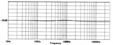
Still not nearly enough for me!when i look at the chart at 1Vrms input you must have 10% of distorsion?
Sent from my phone with Tapatalk. Please excuse any typpos.
I'm wondering if the two sections of a 6P1 can be run in cascaded gain stages without an impedance buffer between them.
I haven't tried it, and wouldn't recommend it for a Hi-Fi application - but it could work well in an effects pedal. Certainly you will get a significant amount of even order distortion as the second section presents a nonlinear load. But if you biased the first stage to have a fairly low plate voltage, and direct coupled to the second, you might get some interesting effects.
Lots of things to try! If I were a guitar guy I'd be all over it
Pete
Just bought one of your boards with tube. Too interesting to pass up. Thanks for all your support of DIY! Hope to get it up and running in a few weeks. Too much work travel for now.
Also, wondering down the line what might be the best approach for a balanced version of this to feed my Hypex amps? Suggestions?
Also, wondering down the line what might be the best approach for a balanced version of this to feed my Hypex amps? Suggestions?
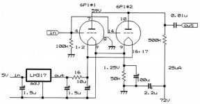
Use four of the stages as in attached schematic. Without the input selector switch and volumpot at output. Schematic optimized for minimal distorsion.
2 for left hot and cold signal and 2 for right hot and cold signal.
And 1 power supply a channel( for 2 stages).
2 for left hot and cold signal and 2 for right hot and cold signal.
And 1 power supply a channel( for 2 stages).
Attachments
Last edited:
NuHybrid Headphone Amplifier
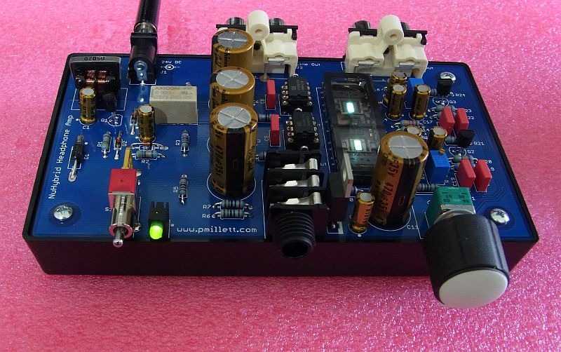
I just published the design of a hybrid headphone amp using the Nutube. You can see all the details here: NuHybrid Headphone Amp
Also selling the PCB (with a Nutube) through my eBay store: DIY PCB plus Tube - NuHybrid Headphone Amp using the Korg Nutube 6P1 | eBay
Pete
I just published the design of a hybrid headphone amp using the Nutube. You can see all the details here: NuHybrid Headphone Amp
Also selling the PCB (with a Nutube) through my eBay store: DIY PCB plus Tube - NuHybrid Headphone Amp using the Korg Nutube 6P1 | eBay
Pete
This is brilliant. I will have to order that as well. So, the question is, with the two RCA line outs on the headphone amp, does it act pretty much like a buffer/line stage and, if so, what is the difference between this line stage output and the original buffer board?
More praise to you for such DIY support!
More praise to you for such DIY support!
This is brilliant. I will have to order that as well. So, the question is, with the two RCA line outs on the headphone amp, does it act pretty much like a buffer/line stage and, if so, what is the difference between this line stage output and the original buffer board?
More praise to you for such DIY support!
Thanks!
The main difference between this and the buffer board:
- Opamps connected for unity gain on the output (to drive 16 ohm headphones)
- Volume control
- Connectors
- Muting relay circuit
The preamp output on RCA connectors is the same as the headphone out, with some 150 ohm series resistors in line. So the maximum gain is about 6x. Of course, you can use the volume control to drop it to 1x, so if you want to try it in front of a regular power amp, this is an easy way to do it.
Pete
The approx $50 entry price could very well be a show stopper for most of us, especially considering that the low gm really limits the applications in which such a tube could be used.
Oh, that and the fact that it does not have the sexy visual factor a lot of people look for in tubes
Oh, that and the fact that it does not have the sexy visual factor a lot of people look for in tubes
Oh, that and the fact that it does not have the sexy visual factor a lot of people look for in tubes
I thought it lights up, as it's based on a display tube. No?
Sent from my phone with Tapatalk. Please excuse any typpos.
The approx $50 entry price could very well be a show stopper for most of us, especially considering that the low gm really limits the applications in which such a tube could be used.
Oh, that and the fact that it does not have the sexy visual factor a lot of people look for in tubes
Very true. But then again, some pay $10 each for exotic resistors...
Hi,
My friends from China complain about its MIC effect. How severe is this?
I agree that $50USD(~5000 JP Yen) is a bit expensive.
It is microphonic. If you tap it, it rings at 5.8kHz, which is quite audible. In a headphone amp or power amp buffer application, I don't think it is a big problem. I wouldn't suggest it in a low-level stage in a mic or phono preamp because of this, though.
I thought it lights up, as it's based on a display tube. No?
Correct. They left the phosphor on the anode of the tube, so it glows with a bluish-white glow. The higher the plate current, the brighter the glow.
Pete
- Status
- This old topic is closed. If you want to reopen this topic, contact a moderator using the "Report Post" button.
- Home
- Vendor's Bazaar
- Korg NuTube is now available online