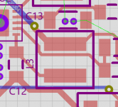
That looks weird! Can you measure that there is input voltage on the left side of the inductor? Should be around 16V. If there is, try to temporarily bridge the inductor with a piece or wire, to see that you have output voltage. If so, it's just the inductor.
But I fear that there has been some sort of overload before the linear post-regulator. Maybe a probe or wire inadvertently falling on the board.
Jan
But I fear that there has been some sort of overload before the linear post-regulator. Maybe a probe or wire inadvertently falling on the board.
Jan
It gets even more weird:
- I measure around 8.6 to 9 V on both sides of the inductor
- the bottom side of the board gets hot, around where the cracker inductor is
- while fiddling around I re-measured the output and I some point I did get -15 on the negative one
Could there be something broken inside L3 that causes intermittent short circuits? Or should I look somewhere else?
It gets even more weird:
- I measure around 8.6 to 9 V on both sides of the inductor
- the bottom side of the board gets hot, around where the cracker inductor is
- while fiddling around I re-measured the output and I some point I did get -15 on the negative one
Could there be something broken inside L3 that causes intermittent short circuits? Or should I look somewhere else?
What you measured around the inductor probably had a lot of ripple, so the value may not be correct.
What I can suggest is if you can short out the inductor. Then output voltages should be OK (but with a bit more HF ripple) and will confirm that L3 is the culprit.
Jan
Attachments
I shorted it by holding a wire to the edges of the pads just protruding on the left side. What is see happening is that the voltage across ground and V- slowly decreases to 0 while I hold the short. As soon as I release, the voltage jumps up again. Currently I have +15 on V+ and -2 on V-. So the -2 slowly creeps to 0 when I short.
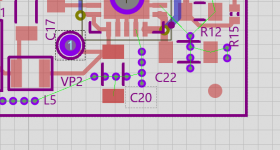
Is that the purple circle above VP2 with the “1” inside? There I measure -2V.
Yes, that means that there is a defect in the switching chip, or the freewheel diode.
Not much you can do, it's pretty much impossible to repair it.
I'll send you a PM tomorrow.
Jan
Jan, how did you end up configuring the SilentSwitcher to run your vicnic oscillator?
I'm planning ahead.
The vicnic specs recommend a PSU delivering +35 VDC / 20 mA. Your SS page, doesn't appear to cover off that detail.
I'm planning ahead.
The vicnic specs recommend a PSU delivering +35 VDC / 20 mA. Your SS page, doesn't appear to cover off that detail.
Jan, how did you end up configuring the SilentSwitcher to run your vicnic oscillator?
I'm planning ahead.
The vicnic specs recommend a PSU delivering +35 VDC / <*> mA. Your SS page, doesn't appear to cover off that detail.
Oops: error from previous post, * = 25
Jan, how did you end up configuring the SilentSwitcher to run your vicnic oscillator?
I'm planning ahead.
The vicnic specs recommend a PSU delivering +35 VDC / 20 mA. Your SS page, doesn't appear to cover off that detail.
Planning ahead separates the men from the boys ;-)
I think I only shorted R23 and R25 to disable the shunts and connected the +15 and -15 points and ground directly to the SS.
Jan
Planning ahead separates the men from the boys ;-)
I think I only shorted R23 and R25 to disable the shunts and connected the +15 and -15 points and ground directly to the SS.
Jan
Ahhh ... I didn't quite get what was going on with the schematic in that regard. I could see the +/-15 V on the schematic but was struggling to see clearly how it translates to the board layout in terms of available pins.
I'll cross check with vicnic before I pull any triggers. Thanks for the tip.
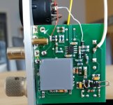
See lower right part. The +/- 15 are across the protection diode.
Jan
Cool. Nice to see the balanced XLR hook up as well.
From the latest schematic at Post #7428:
It looks like you removed R32 and R33 and bridged the connections to the 35V +/-.
I guess that the SilentSwitcher's zero line is connected to the PCB via the white cable. Looks like the -ve lead hole for C14.
Given that R32 and R33 are jumpered, did you simply connect the SilentSwitcher's +/- power to the respective connections on the +/- header pin on the other side of the board?

I don't think I really need to worry about a balanced output for my needs, so I'd stick with the stock single ended approach and keep it simple.
Thanks ..
")
I guess that the SilentSwitcher's zero line is connected to the PCB via the white cable. Looks like the -ve lead hole for C14.
Given that R32 and R33 are jumpered, did you simply connect the SilentSwitcher's +/- power to the respective connections on the +/- header pin on the other side of the board?
Yes!
Jan
They shut down when the input voltage is below 2.7V or so. The current draw from the battery will increase when the battery voltage drops which means the battery is dropping even faster. So the output voltage will remain as set, until it drops out completely.
There's internal output current limiting in the regulator chips.
Jan
There's internal output current limiting in the regulator chips.
Jan
awesome, thank you!They shut down when the input voltage is below 2.7V or so.
- Home
- Vendor's Bazaar
- SilentSwitcher - mains-free +/-15V and 6/5/3.3V power