is it possible to use this chip with single ended inputs? In a traditional CMOY style?? All the datasheet designs are not suitable for this?
OPA1622 can definitely be used in a CMOY style non-inverting op amp circuit (single-ended). I would recommend that the DC resistance at both op amp inputs is matched so that the bias current of the amplifier doesn't create too much offset at the output. But otherwise, there's no problem using the OPA1622 like any other op amp.
Some small updates:
The sample button on the OPA2156 product page should now be working, it should be possible to get prototype units now http://www.ti.com/product/OPA2156/samplebuy
An SOIC package option of the OPA1692 is now released. If you had a project that needed a low power op amp, this package is probably easier to solder than the MSOP package that released first.
http://www.ti.com/product/OPA1692
Some small updates:
An SOIC package option of the OPA1692 is now released. If you had a project that needed a low power op amp, this package is probably easier to solder than the MSOP package that released first.
http://www.ti.com/product/OPA1692
Thank you for the news!!! That's really great... I appreciate the update!
Is there any time for the OPA2145 (Dual OPA145) to be released?
Thank you again, and kind regards!
HL
The only downside I can see with the OPA2156 is its lousy 1/f performance. The knee is at about 1kHz. By comparison the OPA1692 has a 1/f knee at sub 10Hz - which is superb for low noise audio applications.
To give some perspective on the 1/f corner, remember that there is 20 times more bandwidth from 1kHz to 20kHz, than from 1Hz to 1kHz. Or in other words, don't let the log scale fool you in the noise spectral density graph, broadband noise almost always dominates the total integrated noise of a circuit. Phono preamps are the exception to that rule, where the extremely high gain at low frequency makes the circuit more sensitive to 1/f noise.
I should also point out that corner frequencies always look bad in devices with low broadband noise. For example, if we cut the tail current in the input stage of the OPA2156 so the broadband noise was 10nV/rtHz, and left the input device sizes the same, then would the 150Hz corner frequency be impressive? If your broadband noise is high enough, it might look like you don't have a 1/f corner at all, check out the OPA202 datasheet! Compare the OPA2156 to a classic OPA2134, above 300Hz it's pretty clear which is the lower noise amplifier.
Sure the OPA1692 has lower 1/f noise. It uses BJT input devices, so that excellent 1/f performance also comes with roughly 400 fA/rtHz input current noise (20 times more than the OPA2156). Depending on the application this may or may not matter. Alternatively, the OPA164x family of JFET input devices also has better 1/f performance, but the broadband voltage noise is almost double that of the OPA2156.
Don't get me wrong, I'm not saying the OPA2156 (or the upcoming audio version) is the last, best, audio op amp. Rather, its a new addition that brings some very unique features that might be useful in some circuits, namely very low broadband voltage and current noise, very low distortion, and very high output current.
Thank you for the news!!! That's really great... I appreciate the update!
Is there any time for the OPA2145 (Dual OPA145) to be released?
Thank you again, and kind regards!
HL
Thanks for asking, the dual channel version of the OPA145 shouldn't be too far off. Let me check with the team and update here when I know the target date.
John - is there a way to measure modulation noise added by an op-amp (during lifelike payload)? Is there any?
btw- thanks for being around, sharing your knowledge in a friendly manner - appreicated!
//
Could you explain a bit more what you mean by modulation noise?
Happy to be here and contribute what I know!
Hmm. If the goal is to measure this in real time while a realistic signal is being played back (e.g. multiple tones) then I would probably suggest using the common mode rejection of an integrated instrumentation amplifier to subtract the input signal from the device-under-test (DUT) output and viewing the resulting signal in the frequency domain on a spectrum analyzer.
For a linear op amp (not a chopper) without any sort of charge pump or free running oscillator, its hard for me to imagine how a non-harmonically related signal could appear at the output of a properly designed amplifier. I guess high frequency oscillations during transient events might fall into this category, but again those are simulated for in the design process.
Hi,
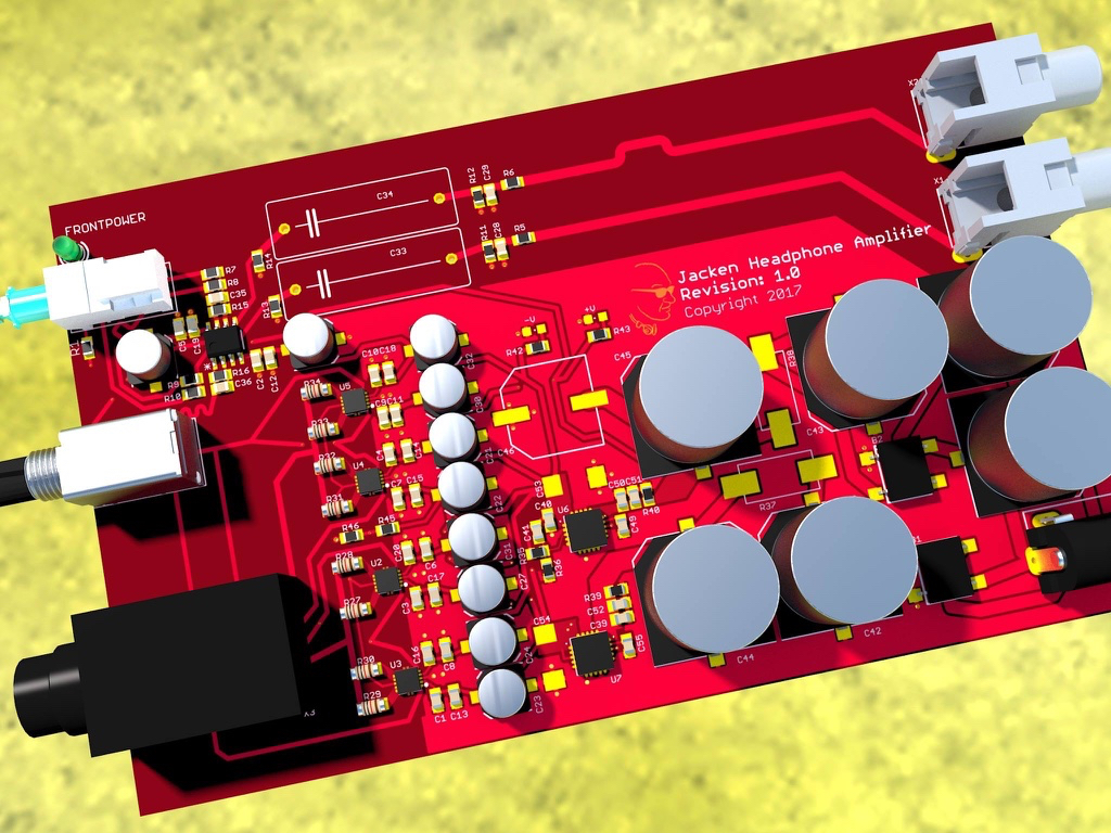
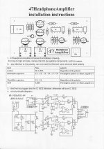
I've looked through the thread but haven't found any mention of using this OPA1622 in a classic 47 amp circuit. This might be because using two op amps is unnecessary for the 1622, although I see Jacken has done four in parallel so maybe it can be a good implementation for basic diyers like me? I also use HD650 so.... I'm curious to try and run them from an LiFePO4 battery pack of about 16.5V. Below are the instructions for the usual cheap kit on Ebay etc. I think I would also like to try a version with a dual rail supply.
I guess the 1622 would like R4/R5 (the feedback loop resistors) to be 2.8K and the R6/R7 to be about 560R for gain of 6? What about the 47R load sharing resistors (R8-11) - what value would be ideal?
Thanks for any/all help!
John, I can now confirm that putting four OPA1622 op amps in parallell works like a dream! When driving 300 Ω Sennheiser HD650, it sounds wonderful. The old version with 2 output driver struggled a bit with high gain, but with four it's working perfectly. Who knew that the HD650 could handle base so well.
Attachments
Last edited:
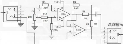
Specifically, any comments on this? (Apart from comments on the obviously crude image, for which I apologise - MS Paint only on this machine). I gather a gain of 7.5 will mean R4 needs a small bypass cap of about 100pF? The output coupling cap will be removed for a split rail supply.
Attachments
- Home
- Vendor's Bazaar
- New Audio Op Amp - OPA1622