The advantages of differential signalling are well-established in the literature and differential connections are standard in professional audio. However, adoption has been slow in home hifi products. The THAT Driver addresses this. The intent of the THAT Driver circuit is two-fold. The circuit can be used to retrofit a differential output to your single-ended source. If fitted with a volume control, it is also ideally suited as a preamplifier for amplifiers with differential inputs, such as the Modulus-86, Parallel-86, DG300B, etc.
The THAT Driver takes a single-ended (unbalanced) input and provides a differential (balanced) output. Many single-ended systems, even the better ones, appear to operate right at the audible threshold for mains hum. The result is a fuzz in the sound due to the intermodulation between the mains hum and the input signal. Using differential signalling, the THAT driver, greatly improves sound quality by practically eliminating this mains hum.
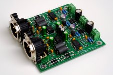
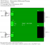
The THAT Driver provides two identical circuits with a shared on-board low-noise power supply regulator, hence, is ideal for stereo and multi-channel builds.
Circuit boards are available for purchase through my website: THAT Driver: Differential line driver / preamp
The specifications for the THAT Driver are listed below.
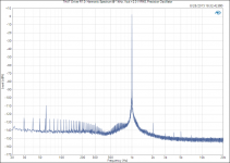
The measurements are shown in the attachments. Note that to measure the THD, a precision oscillator (Victor's 1 kHz) was used. This oscillator does add some spurs at multiples of 30 Hz, hence, they show in the THAT Driver output in this measurement as well.
Tom
The THAT Driver takes a single-ended (unbalanced) input and provides a differential (balanced) output. Many single-ended systems, even the better ones, appear to operate right at the audible threshold for mains hum. The result is a fuzz in the sound due to the intermodulation between the mains hum and the input signal. Using differential signalling, the THAT driver, greatly improves sound quality by practically eliminating this mains hum.
The THAT Driver provides two identical circuits with a shared on-board low-noise power supply regulator, hence, is ideal for stereo and multi-channel builds.
Circuit boards are available for purchase through my website: THAT Driver: Differential line driver / preamp
The specifications for the THAT Driver are listed below.
- Gain: 6.0 dB
- Output Noise Floor: -152 dBV
- Residual Mains Hum: -138 dBV
- THD: 0.000021 % (@ Vout = 2 V RMS)
- THD+N: 0.00032 % (@ 1 kHz, 20 kHz BW)
- THD+N: ≤ 0.0007 % (@ DC – 5 kHz, 60 kHz BW)
- THD+N: ≤ 0.0010 % (@ 20 kHz, 60 kHz BW)
- IMD: SMPTE, 60 Hz + 7 kHz, 4:1: -104 dB
- IMD: 18 kHz + 19 kHz, 1:1: -114 dB
- Gain Flatness: 0.02 dB
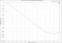
- Bandwidth: 5.7 Hz – 320 kHz (-3 dB)
- Power Supply Voltage: ±18 V – ±40 V
- Power Supply Current: 25 mA
- Board Dimensions: 3.0 x 3.0 inches (76 x 76 mm).
The measurements are shown in the attachments. Note that to measure the THD, a precision oscillator (Victor's 1 kHz) was used. This oscillator does add some spurs at multiples of 30 Hz, hence, they show in the THAT Driver output in this measurement as well.
Tom
Attachments
-
 THAT_Driver_AssembledPCB.jpg423.2 KB · Views: 3,643
 -
 THAT Driver R1.0_ Harmonic Spectrum @ 1 kHz, Vout = 2.0 V RMS, Precision Oscillator.png47.8 KB · Views: 3,583
 -
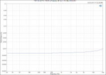 THAT Driver R1.0_ THD+N vs Frequency @ Vout = +18.7 dBu, 60 kHz BW.png36.8 KB · Views: 3,443
 -
 THAT Driver R1.0_ THD+N vs Output Level @ 1 kHz, 22 kHz BW.png28.4 KB · Views: 3,389
 -
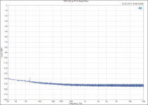 THAT Driver R1.0_ Noise Floor.png35 KB · Views: 3,355
 -
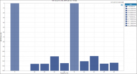 THAT Driver R1.0_ IMD, SMPTE @ Vout = 18.5 dBu.png40.2 KB · Views: 384
 -
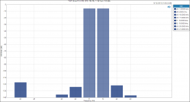 THAT Driver R1.0_ IMD, DFD, 18k_19k, 1_1 @ Vout = 18.5 dBu.png33.6 KB · Views: 310
 -
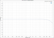 THAT Driver R1.0_ Amplitude Response.png46.3 KB · Views: 312
Attached shows how to configure the THAT Driver as a preamp by adding a volume pot.
Tom
Hi, I'm using a DSP Crossover, and still building (upgrading) my system.
The DSP has three S/PIDF outs, and I have 3 stereo DACs (single ended analog output). I'm thinking that if I put three THAT Driver boards in the same chassis with the three DAC boards, then essentially I'll have 6 balanced XLR connections out to amplifier.
I was thinking of putting a make-before-break stepped attenuater ladder between the analog out of DAC in front of THAT Driver input. 10k log taper, six deck. If I build that with high quality .5% resistors, would that mean it should keep all channels at same level with less variation of dB compared to using 1% or 5% resistors?
Do you see any problem with using a MBB Ladder attenuator as opposed to a more conventional potentiometer?
Another question if I may. The DACs I have seem to have plenty of output. I have not measured yet, but I'm betting they have 1.75 or 2V output. THAT Driver provides 6dB gain. Will I end up with feeding too much power to a Mod86? Sorry if that's a silly question. I know I loose some dB in the DSP, because it's inputs are turned down a little so I don't clip the DAC. I'm trying to understand gain staging and if I'm at the right place in the signal chain to try to get back what I lost without amplifying more noise too.
I'm thinking that if I put three THAT Driver boards in the same chassis with the three DAC boards, then essentially I'll have 6 balanced XLR connections out to amplifier.
Sounds like a good plan.
Do you see any problem with using a MBB Ladder attenuator as opposed to a more conventional potentiometer?
The only drawback of a switch-based attenuator is that the step size tends to be a bit large. As long as this is OK with you, there's no issue with using an attenuator. In fact, you get the absolute best channel-to-channel tracking with an attenuator.
I have not measured yet, but I'm betting they have 1.75 or 2V output. THAT Driver provides 6dB gain. Will I end up with feeding too much power to a Mod86?
If you crank the volume knob all the way to the max and play an album that's recorded to clip at 0 dBFS, then you'll overdrive the MOD86 by about 6 dB.
If, on the other hand, you're playing an album with significant dynamic range - such as the original Dire Straits "Brothers in Arms" album (not remastered) - you'll find the additional 6 dB of gain pretty handy for the times you really want to crank it.
In summary: I wouldn't worry about it.
Tom
I can see the usefulness of this in a pro audio environment were we run balanced signals and long cables. Real advantages there. But how useful would it be at home where single ended is the norm and cables are short? Is it meant for interfacing with balanced input amps, maybe?
- THD: 0.000021 % (@ Vout = 2 V RMS)
- THD+N: 0.00032 % (@ 1 kHz, 20 kHz BW)
- THD+N: ≤ 0.0007 % (@ DC – 5 kHz, 60 kHz BW)
- THD+N: ≤ 0.0010 % (@ 20 kHz, 60 kHz BW)
On which equipment where these figures confirmed??? As far as I know lab-equipment usually does not measure THD under 0.0001%
On which equipment where these figures confirmed??? As far as I know lab-equipment usually does not measure THD under 0.0001%
Why don't you have a look at Tom's site, he clearly states what test eq is used and how the tests were done, levels, bandwidth etc.....
reliable THD measurement under 0.0001% (< -120db)... come on...Why don't you have a look at Tom's site, he clearly states what test eq is used and how the tests were done, levels, bandwidth etc.....
I use an Audio Precision APx525. The instrument itself is good to -112 dB THD+N. For more zeros on the THD measurements, I use a precision oscillator. Search "Victor Oscillator 1 kHz" on this forum (or on eBay). The noise floor of the FFT analyzer in the APx525 is about -160 dBV (512k FFT length, 32 averages). Victor's oscillator is good down to -140ish dB THD.
Tom
Tom
I can see the usefulness of this in a pro audio environment were we run balanced signals and long cables. Real advantages there. But how useful would it be at home where single ended is the norm and cables are short?
That's what I used to think. I then had the opportunity to listen to a fairly nice stereo that offered both balanced (XLR) and unbalanced (RCA) connections. Parasound P3 preamp, Parasound A23 power amps vertically bi-amped on a pair of Dali Suite 2.8 speakers. Pretty nice setup. I honestly didn't expect the balanced connections to make any difference. After all, as you say, the connections are short. I was pretty blown back that I actually was able to tell a difference. The sound cleaned up as if the IMD was suddenly lower.
Now, I should say that this "test" was by no means scientific. It was the standard audio enthusiast sighted A/B test, so the usual disclaimers apply. It did make me wonder if much of the consumer audio equipment is actually operating at the audible threshold for mains or ground loop induced crap. The various ground loops will generate enough crap to create IMD, but not enough to be perceived directly.
Regardless of the cause of the sound quality improvement, I'll take it... The differential signalling also makes it much easier to manage ground loops (yes, you will have some) as the differential signalling essentially moves the ground loop outside the main signal path.
Tom
Last edited:
Have you ever done any THD (without the noise) tests on your designs?
Yeah. I usually measure both THD and THD+N. See Post #1.
Tom
That's what I used to think. I then had the opportunity to listen to a fairly nice stereo that offered both balanced (XLR) and unbalanced (RCA) connections. Parasound P3 preamp, Parasound A23 power amps vertically bi-amped on a pair of Dali Suite 2.8 speakers. Pretty nice setup. I honestly didn't expect the balanced connections to make any difference. After all, as you say, the connections are short. I was pretty blown back that I actually was able to tell a difference. The sound cleaned up as if the IMD was suddenly lower.
Now, I should say that this "test" was by no means scientific. It was the standard audio enthusiast sighted A/B test, so the usual disclaimers apply. It did make me wonder if much of the consumer audio equipment is actually operating at the audible threshold for mains or ground loop induced crap. The various ground loops will generate enough crap to create IMD, but not enough to be perceived directly.
Regardless of the cause of the sound quality improvement, I'll take it... The differential signalling also makes it much easier to manage ground loops (yes, you will have some) as the differential signalling essentially moves the ground loop outside the main signal path.
Tom
I had the same experience. In the late 90's Dad got a Classe' Amp and Preamp, Vandersteen speakers. We listened to it for about a month with single-ended RCA cords (expensive cords I'll add), then he decided to upgrade to balanced XLR cables between amp and pre. Even though they were short cables in a home hifi setup, it was a night and day difference!
Power Supply
So what do you recommend for a Power Supply?
I know it's supposed to be DC +/- 18V to 40V, 25mA
I'm trying to guess what some options are:
Maybe a Power-86 Power-86: Power Supply Board for Modulus-86 with a rather small transformer?
Maybe a wallwort, like a linear, regulated one? Like this one: 24V Power Supply|AC to DC Linear Regulated 24V 0.5A Power Supply
Maybe something like the Jung / Jan Didden "Super Regulator"? Like this: Super Regulator V2.3 - Power Supplies and Accessories - Circuit Boards
Thanks,
AlexQS
A Power-86 board with a, say, 2 x 15 VAC, 10-25 VA transformer would be perfect. Probably a bit overkill in the stock configuration, but replace the stock caps with some smaller (lower height) types would make it a nice and compact option.
You can also go the switching supply route. Mean Well makes some 24 V units that can handle the current. They're pretty competitively priced as well. You'll need to put two of them in series.
A typical wall wart, such as the one you link to only provide a positive voltage. You'll need to provide both +18 V and -18 V, unless you want to get into inverter design, that is.
I don't see any need for fancy supplies. A Power-86 with a transformer or a pair of Mean Well units would work just fine.
Tom
Tom, I received my boards, sooner than expected ") . Great quality. I like that all of the markings on the board are very clear and legible. Looks like a pretty straight forward build.
. Great quality. I like that all of the markings on the board are very clear and legible. Looks like a pretty straight forward build.
Stuff from Mouser should arrive soon.
I may start a thread somewhere, and/or just upload a pic here when it's done. It may be a while though. Unfortunately I won't find time to begin for at least another week
Cheers,
AlexQS
. Great quality. I like that all of the markings on the board are very clear and legible. Looks like a pretty straight forward build.Stuff from Mouser should arrive soon.
I may start a thread somewhere, and/or just upload a pic here when it's done. It may be a while though. Unfortunately I won't find time to begin for at least another week
Cheers,
AlexQS
''Default gain: 6.0 dB (2×). May be increased by resistor options''
Can you get the gain at 0 dB with the resistors on board?
Nope. 6 dB is the minimum gain. That's set by the THAT1646.
Tom
Tom, I received my boards, sooner than expected
Cool! I'm glad you like it.
Tom
Well just about every cartridge is a balanced device. And most DACs are balanced output. And most solid state power amps are push pull output, which functionally is the same as a valve balanced push pull output, except that complementary s-s devices let you do single ended push pull.I can see the usefulness of this in a pro audio environment were we run balanced signals and long cables. Real advantages there. But how useful would it be at home where single ended is the norm and cables are short? Is it meant for interfacing with balanced input amps, maybe?
So, if you are balanced at the source and balanced at the output, why would you want to go single-ended in between?
- Status
- This old topic is closed. If you want to reopen this topic, contact a moderator using the "Report Post" button.
- Home
- Vendor's Bazaar
- THAT Driver :: A minimalistic differential driver / preamp with 0.000021 % THD