Last week TI released a new audio Op Amp, the OPA1688 (http://www.ti.com/product/OPA1688)
For those that are interested, the basic specs are:
Gain Bandwidth Product: 10 MHz
Slew Rate: 8 V/us
Power supply voltage range: (4.5V to 36V or +/- 2.25V to +/- 18V)
Power supply current: 1.6mA
Input voltage noise: 8nV/rtHz (1kHz)
Input current noise: 1.8 fA/rtHz
Input offset voltage: +/- 0.25mV (typical)
Input bias current: +/- 10pA
Input voltage range: 100mV below V- to 2V below V+ (reduced specs outside of this range)
What's really interesting about this device is the output stage linearity, which makes it a good choice for driving headphones. For example, if you're using an OPA2134 in a CMOY-type headphone amplifier, the OPA1688 would be a big improvement in both distortion and power consumption.
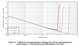
I wanted to know how well it drives headphone-sized load impedances. This is answered in Figure 51 of the datasheet, reproduced below.
_
Thanks for posting Mark. I just wanted to point out that Figure 51 was taken on +/-5V supplies. The maximum output voltage into 600 ohm headphones will be greater if the supply voltages are increased, as is shown in Figure 16 (taken with +/-18V supplies).
typo in fig 49?
johnc124 - I might have found a typo in figure 49 in the OPA1688 datasheet (same diagram is at the bottom of page 1), comparing it with fig 52 in the OPA1622 sheet.
Fig 52 in the 1622 sheet uses 470pF which results in a 3dB point of around 441KHz, if I've done the math right, which would make perfect sense to preserve a flat 100KHz or so audio band. But... fig 49 in the 1688 sheet uses 47pF which would result in a corner of 4.5MHz. Probably not what you guys had in mind. I'll bet the 47 should be a 470.
Also something funny. I went to buy some at Mouser and found they had "SOIC8" listed for all 4 types, even the two VSON8. I reported it and the listing is correct now. Seems that Digikey is only stocking the VSON package.
johnc124 - I might have found a typo in figure 49 in the OPA1688 datasheet (same diagram is at the bottom of page 1), comparing it with fig 52 in the OPA1622 sheet.
Fig 52 in the 1622 sheet uses 470pF which results in a 3dB point of around 441KHz, if I've done the math right, which would make perfect sense to preserve a flat 100KHz or so audio band. But... fig 49 in the 1688 sheet uses 47pF which would result in a corner of 4.5MHz.
Probably not what you guys had in mind. I'll bet the 47 should be a 470.Also something funny. I went to buy some at Mouser and found they had "SOIC8" listed for all 4 types, even the two VSON8.
I reported it and the listing is correct now. Seems that Digikey is only stocking the VSON package.
Last edited:
I had a different goal with that little cap in the OPA1688 applications section. I sized it so that the downward slope it introduces in the inverse feedback factor curve happens right when it intersects the loop gain curve. This gives me a nice little boost in phase margin. Even more confused? I explain this idea in this document: http://www.ti.com/lit/ug/tiduaw1/tiduaw1.pdf . Scroll to the simulation section and read how I size the capacitor for stability.
Basically the same circuit, with some different resistor values. The moral of the story is that the cap in this circuit is there for stability more than bandwidth limiting.
The OPA1688 doesn't have quite the capacitive load drive capabilities of the OPA1622, so this little trick was necessary to give the design suitable phase margin.
Interesting! Thanks for the explanation. I'm preceeding my pot with an RF filter anyway to keep junk out, so the wider BW shouldn't matter, although I may drop the corner frequency of that filter a bit more.
Hey another question comes to mind, turn-on and turn-off pops with the 1688. The 1622 has that nifty enable line with the resistive divider to keep the en below logic threshold while the power rails are coming up. Without something similar on the 1688 am I right that it is going to be more important to keep the power rails tracking closely during power up and down? Or use an output headphone relay with a few second delay, which I've done in a couple of headamp projects.
I'm preceeding my pot with an RF filter anyway to keep junk out, so the wider BW shouldn't matter, although I may drop the corner frequency of that filter a bit more.Hey another question comes to mind, turn-on and turn-off pops with the 1688. The 1622 has that nifty enable line with the resistive divider to keep the en below logic threshold while the power rails are coming up. Without something similar on the 1688 am I right that it is going to be more important to keep the power rails tracking closely during power up and down? Or use an output headphone relay with a few second delay, which I've done in a couple of headamp projects.
Re-reading what I wrote above I should have said "the wider chip bandwidth is going to be OK for my project" because I have a separate input RF filter. Didn't mean to imply there is any problem with the 47pF cap, given the explanation. That was a very well thought-out design and solution for Cload drive stability, from the blog article.
I think what I'm going to do for anti-thump protection is just add a small eletrolytic cap on each rail after the power switch to help force them to come up and go down at more-or-less the same time. Plus it should help de-bounce the power switch. Not low ESR, I want the audio currents to go back through the (presumed more linear) batteries or voltage regulator rather than an electrolytic. In fact I might add an ohm or two in series with the capacitors to make sure the electrolytics are not the primary signal current return path.
Didn't mean to imply there is any problem with the 47pF cap, given the explanation. That was a very well thought-out design and solution for Cload drive stability, from the blog article.I think what I'm going to do for anti-thump protection is just add a small eletrolytic cap on each rail after the power switch to help force them to come up and go down at more-or-less the same time. Plus it should help de-bounce the power switch. Not low ESR, I want the audio currents to go back through the (presumed more linear) batteries or voltage regulator rather than an electrolytic. In fact I might add an ohm or two in series with the capacitors to make sure the electrolytics are not the primary signal current return path.
Last edited:
Re-reading what I wrote above I should have said "the wider chip bandwidth is going to be OK for my project" because I have a separate input RF filter.
I think what I'm going to do for anti-thump protection is just add a small eletrolytic cap on each rail after the power switch to help force them to come up and go down at more-or-less the same time. Plus it should help de-bounce the power switch. Not low ESR, I want the audio currents to go back through the (presumed more linear) batteries or voltage regulator rather than an electrolytic. In fact I might add an ohm or two in series with the capacitors to make sure the electrolytics are not the primary signal current return path.
I think you'll be surprised by the impedance of the batteries, especially 9V batteries. The ones I've measured in the lab showed about 3 ohms of series resistance, this directly turns into even-order harmonic distortion when the op amp delivers large currents to the load. So maybe no resistor in series with those caps on the supplies
johnc124 - interesting about the battery resistance! Was that with 9V primary cells or rechargeable? Some of the conventional wisdom I've seen floating around in various posts over the years is that "9V" NiMH is supposed to be lower resistance than primary cells, then "9V" lithium lower than NiMH. But conventional wisdom is often wrong! Please let me know what type of 9V you tested.
Hmmm... an alternate solution to the electros that would be less frequency sensitive would be LDOs between the batteries and circuit, if I could make some fit. Then the circuit would be looking back into the LDO vreg output Z.
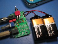
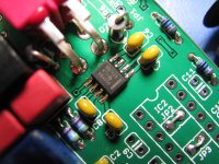
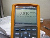
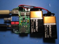
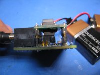
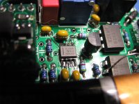
My board arrived back from fabrication today and I have to say the OPA1688 does sound terrific! I've tried it on a few different headphones and they all sound fantastic. Photos below. The meter is the DC output offset, 600uV! Pretty slick. There is indeed a small turn-on turn-off pop, but I've heard a lot worse on headamps. Small enough I probably won't worry about it. I still need to hook it up to the scope and check for oscillations. I used your 47pF, then 1K for Rf and for the resistor from inverting to ground, so a voltage gain of 2.
Please let me know what type of 9V you tested.Hmmm... an alternate solution to the electros that would be less frequency sensitive would be LDOs between the batteries and circuit, if I could make some fit. Then the circuit would be looking back into the LDO vreg output Z.
My board arrived back from fabrication today and I have to say the OPA1688 does sound terrific! I've tried it on a few different headphones and they all sound fantastic. Photos below. The meter is the DC output offset, 600uV! Pretty slick.
There is indeed a small turn-on turn-off pop, but I've heard a lot worse on headamps. Small enough I probably won't worry about it. I still need to hook it up to the scope and check for oscillations. I used your 47pF, then 1K for Rf and for the resistor from inverting to ground, so a voltage gain of 2.Attachments
Last edited:
Great looking project!!!
I was testing non-rechargeable 9V batteries. I did test lithium ions and saw an improvement (can't remember the exact impedance right now) but I remember the elevated 2nd harmonic still being visible in the spectrum when I looked at it on the audio precision (in all cases it was still below -100dB).
I think for CMOY headphone amplifiers the OPA1688 is a no brainer. It has more linear input impedance, better distortion at high output currents, comparable noise, and significantly less power consumption than the OPA2134s which always seem to be used in those projects.
I agree, the OPA1688 just screams "CMOY me!" It is the perfect chip.
I sort of view the OPA1688 as a new and improved NJM4556A, the output chips used in NwAvGuy's O2 headamp and the Grado headamp, which are the only other (older DIP-8) op-amps I'm aware of that can do 75mA per channel out. But that older chip eats 9-12mA quiescent - not battery friendly - and sucks 40nA of input bias current. I can say from measurements I've made that 1.5mV of the typical 3mV output offset on the O2 headamp is that input bias being pulled through the amp's 40.2K ground return resistors. I forgot to say that the 600uV I measured above was with 49.9K ground return resistors between the input of the 1688 and the coupling caps! The FET inputs doing their thing.
The THD+N of the 1688 should be better too, best I can tell comparing the datasheet graphs vs. the O2 dScope measurements that NwAvGuy posted. The voltage noise figure for the NJM4556A *should* be lower, being bipolar input vs. FET on the OPA1688, but strangely it is actually higher at 10nV/sqrt(Hz). The OPA1688 even beats it on noise.
I also suspect the NJM4556A has some input impedance distortion that happens at mid volume control, with essentially 2.5K in series with the chip's input (10K pot on the O2 headamp). NwAvGuy did all his dScope measurements with the pot all the way up, so I never have been able to prove it. Good to know the OPA1688 doesn't have any significant input impedance distortion issues. No worries about putting a pot in front of it.
An interesting thing popped up from my weekend (OPA1688) datasheet re-reading, I had missed the extent of the built in EMI filtering, section 9.3.1. You guys have built-in rejection into the GHz cell phone bands! Pretty amazing. That is a known problem with the O2, cell phone interference pickup if within near-field range. Cell phone EMI is a real-world thing CMOYs will likely run into. Folks with the cell phone clipped onto the same pocket the CMOY is in, with the headphone/IEM cable running up from the pocket right by the cell phone.
It is the perfect chip. I sort of view the OPA1688 as a new and improved NJM4556A, the output chips used in NwAvGuy's O2 headamp and the Grado headamp, which are the only other (older DIP-8) op-amps I'm aware of that can do 75mA per channel out. But that older chip eats 9-12mA quiescent
- not battery friendly - and sucks 40nA of input bias current. I can say from measurements I've made that 1.5mV of the typical 3mV output offset on the O2 headamp is that input bias being pulled through the amp's 40.2K ground return resistors. I forgot to say that the 600uV I measured above was with 49.9K ground return resistors between the input of the 1688 and the coupling caps! The FET inputs doing their thing. The THD+N of the 1688 should be better too, best I can tell comparing the datasheet graphs vs. the O2 dScope measurements that NwAvGuy posted. The voltage noise figure for the NJM4556A *should* be lower, being bipolar input vs. FET on the OPA1688, but strangely it is actually higher at 10nV/sqrt(Hz). The OPA1688 even beats it on noise.
I also suspect the NJM4556A has some input impedance distortion that happens at mid volume control, with essentially 2.5K in series with the chip's input (10K pot on the O2 headamp). NwAvGuy did all his dScope measurements with the pot all the way up, so I never have been able to prove it. Good to know the OPA1688 doesn't have any significant input impedance distortion issues. No worries about putting a pot in front of it.
An interesting thing popped up from my weekend (OPA1688) datasheet re-reading, I had missed the extent of the built in EMI filtering, section 9.3.1. You guys have built-in rejection into the GHz cell phone bands! Pretty amazing. That is a known problem with the O2, cell phone interference pickup if within near-field range. Cell phone EMI is a real-world thing CMOYs will likely run into. Folks with the cell phone clipped onto the same pocket the CMOY is in, with the headphone/IEM cable running up from the pocket right by the cell phone.
Last edited:
The OPA1688 will show a slight increase in distortion at high source impedances (gain of +1) and high frequencies but the performance is actually comparable to the older Burr-Brown DiFET parts (e.g. OPA627), I show measurements here: http://www.diyaudio.com/forums/vendors-bazaar/283672-new-audio-op-amp-opa1622-9.html#post4636374
As to the EMI point: unfortunately "low noise bipolar" and "EMI hardened" don't really go together. But JFET and CMOS input devices are significantly more robust in this regard.
As to the EMI point: unfortunately "low noise bipolar" and "EMI hardened" don't really go together. But JFET and CMOS input devices are significantly more robust in this regard.
Using the OPA1622 as a VG for the OPA1688
johnc124 - yet another question. Thanks for the help.
Long story short, are you aware of any problems with using one channel of an OPA1622 as a virtual ground for both channels of an OPA1688? I would use either a 50/50 resistive divider on the OPA1622 input, noise bypassed to ground with a cap, or a TLE rail splitter chip. Don't know what I would do with the other half of the 1622, probably just unused or wired up as a low-battery comparator to turn on a low-battery LED.
details...
I completely forgot about the issue in using +/- dual "9V" batteries of one battery coming unhooked, going into cutoff (internal battery mgmt chip), internally shorting, etc leaving one power rail up and one rail down. The results from some tests today: no +battery = -0.9Vdc out; no -battery = positive battery minus 0.8Vdc out, or about +7.3Vdc out for the batteries I was using. Too risky to use if direct coupled to headphones.
Which reminds me why people use virtual grounds in these things, despite the various problems with virtual grounds and almost certain increase in distortion, crosstalk, noise etc. At least if the now-single battery has a loose contact or shorts, the whole thing just looses power at the same time. Plus that opens up the possibility of using the two 9V batteries in series, so it is back to +/-9V the hard way, with a VG rather than a real ground
NwAvGuy created a "power mangement" circuit in the O2 headamp using a series pass mosfet on each rail and a couple of comparators to solve the problem by cutting off the batteries when low or missing, but unfortunately it never worked well enough to be worth replicating.
So I was thinking what chip can I use for a virtual ground that can source/sink the 75mA + 75mA = 150mA(max) for the two OPA1688 channels and still have excellent AC properties for source & sink, at least as good as the OPA1688... and the OPA1622 came to mind.
Best I can tell from the OPA1622 datasheet, if it lost a rail when used as an amplifier chip there would likely be significant DC on the output too, even with the EN pin (?)
I would expect that the net result of a OPA1688 amp + OPA1622 VG would still beat an existing OPA2134 + TLE2426 VG combination in most specifications.
Last edited:
...and in altering the layout today to make the OPA1622 a virtual ground for the OPA1688, rather than a looped buffer, I realized the 1622 has to operate singled ended. But I know that is OK now as per your post 162 in your OPA1622 thread, just with a PSRR reduction. Ground pin to Vee, EN to Vcc. Lol, interesting that relatively little changes with a 4 layer board. Vcc and Vee planes stay as is (+battery and -battery). The feed point for the ground plane just changes from the 2 battery center connection to one output of the OPA1622 chip.
I see the slew rate of the OPA1622 is slightly higher than the OPA1688 too, which is probably good. I've never seen anythning in print about that regarding virtual grounds, but my gut tells me the VG should have a higher slew rate than the signal it is being asked to follow.
One more question on where the bypassing goes. I'm treating the OPA1622 running as VG as single ended, so no bypass cap on Vee and a 0.1uf from Vcc to Vee. As for the OPA1688 amplifier chip my inclination is to do the same. But over the years in headamps with VGs I've seen many folks bypass the power pins of the amplifier chip to the virtual ground, treating it like a real ground. That has never computed for me. Why bypass rail noise to a virtual ground. In my view of it the VG is just a signal reference point. The power reference point is still Vee (- battery). Any insights here on the correct way to do it are appreciated.
Last edited:
OPA1688 sims great as VG, OPA1622 not so much
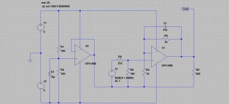
Well here is something interesting. I've installed the OPA1688 and OPA1622 pspice models from the TI website into LTspice.
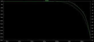
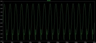
In the first schematic, transient plot and AC plot below an OPA1688 is used for both the amp chip and the virtual ground. Sims great. This is at 20KHz with a 600R load. I didn't attach it but a 32R load also works just fine, with the expected slightly additional loading showing. Magnitude and phase flat as a board through 100KHz.
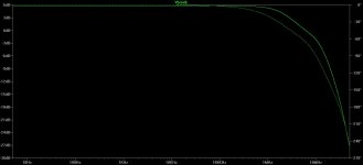
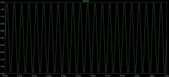
But... The second print, trans plot and AC plot are now with the OPA1622 as VG. The sim is not happy. The AC plot does fine but the transient plot has some sort of glitch near the negative rail. I've tried a few things but so far no luck on eradicating it. I'm just curious if that is purely a simulation model glitch or something present in the real chip when used as a VG. This is with 600R, the OPA1622 VG won'[t sim at all with 32R. Locks right up.
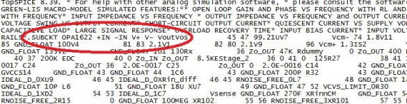
Also curious that the OAP1622 spice model does not appear to have a ground or enable! Snippet below. Enable I can understand, but I'm wondering how that model functions correctly without the chip's ground pin.
It looks like the OPA1688 might make a fine VG!
Something that relates to the discussion in the OPA1622 thread on class A biasing. If I'm thinking about things right here, a virtual ground could probably just be thought of as an exteme, dynamic, form of class A biasing on the VG chip's otuput stage. The load's return signal is effectively a current sink/source operating at audio frequencies rather than being constant.
Well here is something interesting. I've installed the OPA1688 and OPA1622 pspice models from the TI website into LTspice.
In the first schematic, transient plot and AC plot below an OPA1688 is used for both the amp chip and the virtual ground. Sims great. This is at 20KHz with a 600R load. I didn't attach it but a 32R load also works just fine, with the expected slightly additional loading showing. Magnitude and phase flat as a board through 100KHz.
But... The second print, trans plot and AC plot are now with the OPA1622 as VG. The sim is not happy. The AC plot does fine but the transient plot has some sort of glitch near the negative rail. I've tried a few things but so far no luck on eradicating it. I'm just curious if that is purely a simulation model glitch or something present in the real chip when used as a VG. This is with 600R, the OPA1622 VG won'[t sim at all with 32R. Locks right up.
Also curious that the OAP1622 spice model does not appear to have a ground or enable! Snippet below. Enable I can understand, but I'm wondering how that model functions correctly without the chip's ground pin.
It looks like the OPA1688 might make a fine VG!
Something that relates to the discussion in the OPA1622 thread on class A biasing. If I'm thinking about things right here, a virtual ground could probably just be thought of as an exteme, dynamic, form of class A biasing on the VG chip's otuput stage. The load's return signal is effectively a current sink/source operating at audio frequencies rather than being constant.
Attachments

Last edited:
Fantastic sound from the OPA1688!
I've received a V2.0 board of an amp using the OPA1688 a few days ago and just finished the build and test. I've solved the dual battery issue by using solid state relays and a comparator to cut off the batteries if one "disappears" due to bad connection, internal short, protection chip cutoff, low battery, etc. Both rails switch at exactly the same time, which I've noticed reduced the on/off thump issue even without output muting. That is unlike NwAvGuy's O2 Headamp battery cutoff circuit using discrete mosfets with a slight delay between their on/off times due to the control circuit. No virtual ground needed - back to a true ground. I managed to find some SSRs with a tiny 0.05 ohm "on" resistance.
And the results - WOW! Not so much my circuit, the OPA1688 chip. In engineering terms neutral, in audiophile terms excellent bass, treble and finely detailed with a wide soundstage.
One hiccup, this one was optionally going to wrap around a plug-in OPA1622 chip/board. So far the LT Spice simulations I've done say that the looped combination is not stable, at least not without some additional compensation to restore some phase margin. So instead the plug-in board here uses two more SSRs as a muting circuit for absolutely zero turn-on thump and negligible turn-off thump. With the huge 75mA output per channel from the OPA1688 there really isn't much need for an additional current buffer anyway.
I would highly recommend the OPA1688 for headphone amplifiers. Good job johnc124 and TI!
Attachments
Last edited:
I'm glad to see your project is coming along! Sorry for the lack of replies here, I've been traveling quite a bit and haven't had the time to write a response. Although I do try to keep an eye on this thread and the OPA1622 thread.
The solid-state relays are a creative solution to this problem. I've also seen schottky diodes to ground (reverse biased in normal operation) on the supply pins used to protect amplifiers during power-up.
As for the LTSpice simulation hiccups, I can't say I'm surprised. The internal Spice macromodel architecture we use often gets quite complicated since we try to model a large number of the op amp characteristics. A lot of manufacturers are still using the simple "Boyle" macromodel architecture, which doesn't tell you much of anything outside of basic circuit functionality. I have to laugh when I seen folks simulating the distortion of an op amp behavioral macromodel... Unfortunately, what we've found is that TINA is quite accomodating in terms of simulation convergence, where other simulators are not. So we're currently refining our architecture to be friendlier to all simulators.
Thanks for the positive comments on sound quality. I thought the OPA1688 was a fantastic addition to the CMOS audio amplifier family which only had the OPA1652 and OPA1654 previously. The real question now is: what comes next?
Last edited:
Electrolytics on the power rail increase distortion products
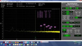
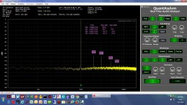
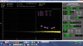
So here is a good reason to keep electrolytic capacitors off the regulated (or battery in this case) power rails - some increased distortion products. I finally had all the pieces together to do these tests today. A (2x 9V with real ground) battery powered audio amplifier using the OPA1688 and the new QA401 audio analyzer.
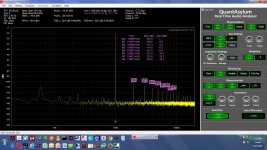
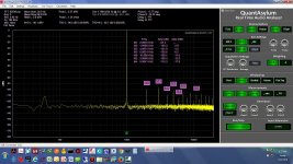
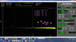
The first 3 plots below are the analyzer in loopback at -10dBV, -1dBV, and +3dBV. This particular analyzer already produces quite a bit of 2nd, 3rd adn 4th harmonics itself that have to be subtracted out of the results.
The next 3 are with the OPA1688 powering a 32R resistive load at the same 3 input levels: -10dBV, -1dBV, and +3dBV. This is with no electrolytic capacitors on the power rails, just the batteries going through a solid state relay with opto-mosfets.
Teh final 3 are the same as above, but with a 22uF 25V low ESR electrolytic capacitor added to each power rail. Wow.... In those last two, -1 and +3dBV, the capacitors seem to be taking some energy from the 2nd, 4th, 5th harmonics and shoving it all into the 3rd.
The thinking in adding the electrolytics was maybe they would help balance the rails during the turn-on rise and shut-off drop to help reduce pops. Nope, doesn't do that either, makes them worse. But the good news here is the pops really are not that bad to start with for the OPA1688.
Clicking on the arrows in the lower left of any of these will zoom them up larger.
So here is a good reason to keep electrolytic capacitors off the regulated (or battery in this case) power rails - some increased distortion products. I finally had all the pieces together to do these tests today. A (2x 9V with real ground) battery powered audio amplifier using the OPA1688 and the new QA401 audio analyzer.
The first 3 plots below are the analyzer in loopback at -10dBV, -1dBV, and +3dBV. This particular analyzer already produces quite a bit of 2nd, 3rd adn 4th harmonics itself that have to be subtracted out of the results.
The next 3 are with the OPA1688 powering a 32R resistive load at the same 3 input levels: -10dBV, -1dBV, and +3dBV. This is with no electrolytic capacitors on the power rails, just the batteries going through a solid state relay with opto-mosfets.
Teh final 3 are the same as above, but with a 22uF 25V low ESR electrolytic capacitor added to each power rail. Wow....
In those last two, -1 and +3dBV, the capacitors seem to be taking some energy from the 2nd, 4th, 5th harmonics and shoving it all into the 3rd. The thinking in adding the electrolytics was maybe they would help balance the rails during the turn-on rise and shut-off drop to help reduce pops. Nope, doesn't do that either, makes them worse. But the good news here is the pops really are not that bad to start with for the OPA1688.
Clicking on the arrows in the lower left of any of these will zoom them up larger.
Attachments
-
 OPA1688 1KHz -1dBV input 32R load with 22uF.jpg252.1 KB · Views: 151
 -
 OPA1688 1KHz -10dBV input 32R load with 22uF.jpg254 KB · Views: 150
 -
 OPA1688 1KHz +3dBV input 32R load.jpg280.8 KB · Views: 136
 -
 OPA1688 1KHz -1dBV input 32R load.jpg251.3 KB · Views: 155
 -
 OPA1688 1KHz -10dBV input 32R load.jpg252.1 KB · Views: 167
 -
 QA401 loopback +3dBV.jpg245.3 KB · Views: 156
 -
 QA401 loopback -1dBV.jpg248.5 KB · Views: 213
 -
 QA401 loopback -10dBV.jpg247.4 KB · Views: 297
 -
 OPA1688 1KHz +3dBV input 32R load with 22uF.jpg252.7 KB · Views: 182
Last edited:
- Status
- This old topic is closed. If you want to reopen this topic, contact a moderator using the "Report Post" button.
- Home
- Vendor's Bazaar
- New Audio Op Amp - OPA1688