Could someone list the base features that the devices can offer (indicate the differences):
Sorry if the question has already been raised before, but it is difficult to find the answer in the thread..
Thanks!
USB DAC V1.0 MAIN Board : 169€
USB DAC V1.2 with simple frontpanel + encoder + IR Receiver : 428€
Sorry if the question has already been raised before, but it is difficult to find the answer in the thread..
Thanks!
Could someone list the base features that the devices can offer (indicate the differences):
Sorry if the question has already been raised before, but it is difficult to find the answer in the thread..
Thanks!
Later today... Around 17.00 gmt i will try to make a list of features
- sonny
Hi all.
I have a found a small bug in the software for display/dac. Sometimes it does not show the correct samplerate. I know where the issue is, and the firmware should be running tonight.
Boards are ready to ship out. I just wanted to fix this small bug, before sending it out so that it does not start we a need for a firmware update.
BR
Sonny
I forgot to say that i have spoken with volumio about integrating oled display and dac with volumio
Sonnya, what do you mean?
Are you going to integrate your dac in the volumio firmware so that hardware settings like volume control can be done through the volumio user interface?
Sonnya, what do you mean?
Are you going to integrate your dac in the volumio firmware so that hardware settings like volume control can be done through the volumio user interface?
Yes that is some of the thoughts. We have all the signals in the 30 pin FFC connector. So we only need a patch board to connect to the uart on the RPI.
I am working on the documents for the DAC and preamp right now.
Many has asked about current consumption of the DAC and Preamp.
The USB DAC V1.2 uses the following:
+5.5 to 7V : 350mA
+15V : 10mA (References for the DAC)
-15V : 0 mA
Discrete output stage:
SE: +/-15V 50mA
XLR:+/-15V 100mA
Preamp discrete board V1.1:
+5V - +5.5V : 100mA
+/-15V : 150mA
Many has asked about current consumption of the DAC and Preamp.
The USB DAC V1.2 uses the following:
+5.5 to 7V : 350mA
+15V : 10mA (References for the DAC)
-15V : 0 mA
Discrete output stage:
SE: +/-15V 50mA
XLR:+/-15V 100mA
Preamp discrete board V1.1:
+5V - +5.5V : 100mA
+/-15V : 150mA
Hi all. I am working hard on the documents.
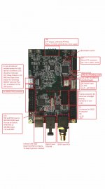
But i have given an overview of the connectors on the board. And it is very versatile.
Have a look. And feel free to ask.
The u.fl. to I2s will fit on J8 and accepts I2S PCM only up to 192KHz/24Bit.
USB is up to PCM 384KHz/32Bit and DOP128 or DSD256 (Native)
RX2 and RX4 on J23 is up to 192KHz/24Bit. They are not enabled in the software but it is easy done.
Attachments
Last edited:
Should arrive later this week.The u.fl. to I2s board should ship out together with the dac board.
Hi all. I am working hard on the documents.
But i have given an overview of the connectors on the board. And it is very versatile.
Have a look. And feel free to ask.
The u.fl. to I2s will fit on J8 and accepts I2S PCM only up to 192KHz/24Bit.
USB is up to PCM 384KHz/32Bit and DOP128 or DSD256 (Native)
RX2 and RX4 on J23 is up to 192KHz/24Bit. They are not enabled in the software but it is easy done.
Sonnya,
looking at the picture could you elaborate more on J13 pins?
It is a 3 pin connector, one pin is “…open drain output for switching ON-OFF external PSU…” as you wrote.
My understanding is that this pin is normally floating and that DAC V1.2 can put this pin to ground, but it is not clear what kind of event triggers it.
Maybe a signal on one of the inputs (usb – spdif- toslink) ?
Please explain.
Thanks.
I have attached a schematic of that section.
J13 and J11 is taken directly across U15 DC/DC converter. If that is to noisy for your taste, you can provide an external power source.
J13 can drive a relay with 5V coil. Just remember the diode (1N4148/1N4004 - 1N4007 .. any standard diode) across the relay coil or the mosfet gets destroyed. (J13:1 +5V, J13:2 Enable by shorting J13:2 to GND through the mosfet, J13:3 GND)
The schematic shows how to connect an external power source.
Attachments
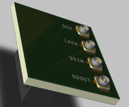
UFL to I2S adapter:
Is this board included with the DAC main board or is sold separately ?
Are you going to provide also the u-fl cables ?
Since it will be mounted in the free space between the dac and the output stage board are there some requirements in terms of height for standoff and J18 connector ?
- Home
- Vendor's Bazaar
- AK4490 USB Dac with dsd support.