Hi cOz,
Do you have the Softstart layout diagram version 1.2?
In this diagram it states that the center pin of the output is a dummy pin used for center of 230Vac.
View attachment 729385
Thanks
Do
Thanks Do - I have been looking for this exact document to better understand the purpose of the "Dummy for Center" I've got it now and will save it to my documents of the build.
Thanks,
Robert
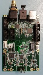
Here is a sample of My own se ond build View attachment 707278 View attachment 707279
What size chassis standoffs do you all use?
Thanks,
Robert
I am sorry i have been out for a couple of days.
Got home yesterday evening.
AnthonyA: What is the source when you have the problems?
cOz: 8mm standoff
Thanks Sonnya I’ve finished assembly today and will bias it this weekend. I’ve had a lot of questions and a few moments of frustration due to my own lack of understanding but now feel great about being able to tackle this project. I’m documenting it from a true novice point of view and will be happy to share my perspective to other newbies. The DIY community is really lucky to have people like you sharing their wares and making them available. I know it’s hard work on your part but please don’t loose your drive and spirit.
Mirand A1 V1.2 - Google Drive
Last edited:
Hello,
I've been helping my friend cOz with adjusting the amp (by chat only), bias and offset. But he ended up measuring quite different offset on L R channels.
I am a bit more experienced but still not exactly an expert, and not having a schematic I thought, better ask.
However trim procedure seems easy in steps it's a bit confusing when you compare parts of the manual so I have put them in one place in picture.
Please comment the picture
Attachments
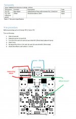
Offset check with Green marking is correct. Between J22 and J24. It cannot pull 100% because the offset has a weak push/pull not to mask the sound too much.
J21 and J23 is bias. mV(J21-J23)/0.4=bias current in mA.
BR
Sonny
Check your text in trim procedure part in manual! You don't mention J21-J23 but J21-J22
Check your text in trim procedure part in manual! You don't mention J21-J23 but J21-J22
Both goes
J21 and J23 will be mV/0.2=mA DC
Hello,
I've been helping my friend cOz with adjusting the amp (by chat only), bias and offset. But he ended up measuring quite different offset on L R channels.
I am a bit more experienced but still not exactly an expert, and not having a schematic I thought, better ask.
However trim procedure seems easy in steps it's a bit confusing when you compare parts of the manual so I have put them in one place in picture.
Please comment the picture
Huge thanks to Bassivus for helping me out, this is what DIY Audio is all about!
Quick update:
J21 and J22 are stable at 10mV and heat sinks are barely above body temperature
J22 and J24 fluctuate but are never above 5mV and often under 1mV
According to the Documented Trim Procedure the amp should be ready to use.
The one last check and some confusion is measuring DC Offset at the RCA plug on the rear chassis. Left channel measures 0mV and right channel 33mV.
What else should be checked before connecting to mutli-thousand dollar DAC and Speakers?
Thanks,
Robert
Good news, I had a fault in RCA and once fixed the amp is singing well. So far I like it!!!

My setup is Modwright Transporter and Salk WOW1... Bassivus and I have been building these together Ceramica hence the need for a reference amp. Thanks to all that helped get me this project completed.
My setup is Modwright Transporter and Salk WOW1... Bassivus and I have been building these together Ceramica hence the need for a reference amp. Thanks to all that helped get me this project completed.
") BR Per
BR PerGood news, I had a fault in RCA and once fixed the amp is singing well. So far I like it!!!
My setup is Modwright Transporter and Salk WOW1... Bassivus and I have been building these together Ceramica hence the need for a reference amp. Thanks to all that helped get me this project completed.
I have checked up on the documentation. And of course you can have DC offset on the input. Because it is bipolar input. so there is a bias current flowing through the basis of the transistors and the input will never be 100% zero.
BR
Sonny
I am sorry i have been out for a couple of days.
Got home yesterday evening.
AnthonyA: What is the source when you have the problems?
cOz: 8mm standoff
Hi. Source is usb. Allo.
I also tried via USB via odroid. Same.
Hi.
A lot of people has not heard from me in a very long time.
Tonight i have been testing the DAC which i have had for several month. Actually since october but never got to the point of actually testing it for release. For many reasons i would not come into here.
The clock domain was upgraded as well as the DAC section. i.e. AK4493+new regulators. The DAC is code compatible with the AK4490.
The clock where changed from Crystek to another type which has nearly the same specs. Instead each crystal has its own Ultra low noise voltage regulator and its own clock divider for feeding into the USB and the SRC4392. Pricewise close to zero difference when we take assembly into account.
So the only thing we needed to test was the clock domain if it works,
And it does work. Before we could see some artifacts for 192KHz which was not a harmonic of the signal. But a constant very very low tone at around 3KHz.
It is done and the noise floor is very low even if the DAC chip runs from 5V reference instead of 6V reference.
The measurements where attached and they speaks for them self.
Yes it is dropbox links as they are 6Mbyte per picture and they are safe to load.
Dropbox - sito usb dac v12a 176400 1k.bmp
Dropbox - sito usb dac v12a 192000 1k.bmp
I have told Margit to start making a list of parts needed for assembly so that we can build and ship them out,
Attachments
Last edited:
- Home
- Vendor's Bazaar
- AK4490 USB Dac with dsd support.