Mute Circuit
I purchased the DAC V1.0 and the output shield Diff/SE V1.0 a while back and just got around to hooking some AMB power supplies to it. My Mac Mini recognizes it, and I have selected it as the output device, but no music comes forth. The Differential Shield instructions say to put +3 to +15 VDC to pin 4 of J7. I have not done this, so is the DAC in mute mode? If this is the case, what is the easiest way to put power to pin 4?
I purchased the DAC V1.0 and the output shield Diff/SE V1.0 a while back and just got around to hooking some AMB power supplies to it. My Mac Mini recognizes it, and I have selected it as the output device, but no music comes forth. The Differential Shield instructions say to put +3 to +15 VDC to pin 4 of J7. I have not done this, so is the DAC in mute mode? If this is the case, what is the easiest way to put power to pin 4?
I purchased the DAC V1.0 and the output shield Diff/SE V1.0 a while back and just got around to hooking some AMB power supplies to it. My Mac Mini recognizes it, and I have selected it as the output device, but no music comes forth. The Differential Shield instructions say to put +3 to +15 VDC to pin 4 of J7. I have not done this, so is the DAC in mute mode? If this is the case, what is the easiest way to put power to pin 4?
Hi,
The manual is here
http://mirand-audio.dk/wp-content/uploads/2015/06/MIRAND-USB-DAC-V10-document-release-010615.pdf
You need +/-15Vdc for the output stage and +5.5Vdc for the DAC.
See manual POWER input J7 connector
Thanks
Do
These two panels are designed together.. if you had plugged them together properly, the mute signal is passed through the connector to the shield, and should work.
Are your power distributed ok? You enter with the power supply onto the schield first, then you take the short second jumper down to the dac board.?
Ciao, George
Are your power distributed ok? You enter with the power supply onto the schield first, then you take the short second jumper down to the dac board.?
Ciao, George
Thanks Dominic..
The two boards should be plugged together at J10.
It contains also the 'mute' signal.
There is no mute signal in J7. It is the power connector.
On the schield, above, the equivalent of J7 is repeated twice.
The external PS (all five cables) should "land" on one of the J7 replica. The other, the second one closer to the 'real J7' on the dac board itself, should be connected with a short run to the dac board.
Hope you can figure out...

Mute Circuit
Thanks everyone for your input. My boards came bolted together, with the jumper cable in place, so that should be okay. I think I may see the problem in the picture that Do posted. I may have my power connector wired improperly.
When I am looking at the top of the shield with the two 5 pin headers closer to me, and the USB input on the left, is pin 1 on J6 on the left or the right? I wired as though pin 1 was on the left. From the photo it looks like Do wired his as though pin 1 is on the right.
Dan
Hi Sonny,
I would really really love to see the DSD direct option added to the Mirand 1.0 with preamplifier. It seem to be a bit to set when enabled. I’m a real fan of your DAC and wish this can be added. I would not mind paying for a software update that would enable this.
Is this something that would require lots of coding?
Thanks for your support
Do
As Sonny knows it so well: we are in two with this request..
Although with sligthly different configurations, I am using the dac in a 'headless' mode with appropriate firmware.
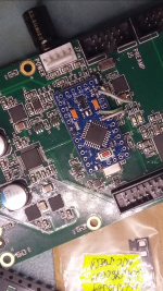
Right now, to get the dac in dsd-direct mode, I'm using this hardware hack with an arduino
Although with sligthly different configurations, I am using the dac in a 'headless' mode with appropriate firmware.
Right now, to get the dac in dsd-direct mode, I'm using this hardware hack with an arduino
Attachments
Hi Sonny , you have an email from me.
Thank you.
I am sorry that i have not have time to answer you.
I have been working on firmware for the ak4490 USB dac. I get back to you later today.
I have made a firmware for the DAC..
Also there is a new windows driver, and it is needed for firmware upgrade.
Dropbox - XMOS-Stereo-USB-Audio-Class2-Driver-30C7_v4.13.0.exe
under Program Files -> XMOS ->USBAudioStDriver_30C7 -> W10_x64
you will find the xmosusbaudiost30C7_dfuapp.exe that is used for firmware upgrade.
Also there is a new windows driver, and it is needed for firmware upgrade.
Dropbox - XMOS-Stereo-USB-Audio-Class2-Driver-30C7_v4.13.0.exe
under Program Files -> XMOS ->USBAudioStDriver_30C7 -> W10_x64
you will find the xmosusbaudiost30C7_dfuapp.exe that is used for firmware upgrade.


I have made a firmware for the DAC..
Also there is a new windows driver, and it is needed for firmware upgrade.
Dropbox - XMOS-Stereo-USB-Audio-Class2-Driver-30C7_v4.13.0.exe
under Program Files -> XMOS ->USBAudioStDriver_30C7 -> W10_x64
you will find the xmosusbaudiost30C7_dfuapp.exe that is used for firmware upgrade.
Thanks for your work.
The link points to the application sw needed to upload the firmware but there are no bin files (like we did in the past).
Is it correct?
Do we have to do something also on the front panel ? (I already have it flashed with the firmware used with the preamp)
- Home
- Vendor's Bazaar
- AK4490 USB Dac with dsd support.