Hi David,
Excellent ! I hope that you will be able to solve the anoying A/D hardware bug...
Best from France
Jean Claude
Unfortunately the ADC is at its end of life phase which means it is not recommended for new designs. Apparently ESS have new ADC's coming out soon and hopefully they will be pin compatible with the old one otherwise I will have to redesign the board again and I cannot currently find out whether the pin-outs are the same on the new devices

cheers
Last edited:
Hi David,Unfortunately the ADC is at its end of life phase which means it is not recommended for new designs. Apparently ESS have new ADC's coming out soon and hopefully they will be pin compatible with the old one otherwise I will have to redesign the board again and I cannot currently find out whether the pin-outs are the same on the new devices
cheers
Thanks for the update. I'm afraid it will take at best months before we can see anything from them documented and really available. So I'm wondering what could be the alternative to you beside a re engineering of the main board with a split of the ADC block ?

Unfortunately the ADC is at its end of life phase which means it is not recommended for new designs. Apparently ESS have new ADC's coming out soon and hopefully they will be pin compatible with the old one otherwise I will have to redesign the board again and I cannot currently find out whether the pin-outs are the same on the new devices
cheers
That is a real bummer. I guess this will take a long while, which seems a shame as you seemed to be getting quite close. What are your and now? Maybe a modular ADC add-on at a later date?
Stefan
I have maybe missed it, but is it a samplerate converter on the input of the DSP? Is it freeware in Audio Weaver?
Sample Rate Converter | DSP Concepts
It would be nice to only make one filter and not one for each input samplerate.
Regards Torgeir
Sample Rate Converter | DSP Concepts
It would be nice to only make one filter and not one for each input samplerate.
Regards Torgeir
I have maybe missed it, but is it a samplerate converter on the input of the DSP? Is it freeware in Audio Weaver?
Sample Rate Converter | DSP Concepts
It would be nice to only make one filter and not one for each input samplerate.
Regards Torgeir
Not needed as the DSP has an inbuilt SRC and everything is referenced to a 192KHz sample rate
cheers
That is a real bummer. I guess this will take a long while, which seems a shame as you seemed to be getting quite close. What are your and now? Maybe a modular ADC add-on at a later date?
Stefan
I'm kind of hoping that whatever they come out with will be a drop-in replacement for the existing ADC but failing that there are some other options from other vendors that I could consider which also offer high performance.
cheers
Much much better. I don't think there willl be anything currently on the market that will compete.
Stefan
I became interested in the Linkwitz LX521 speaker system. Then they stopped making the ASP board and went to DSP, using a MiniDSP box. I feel the 96 kHz sample rate would be a compromise compared to the analog crossover. Analog can have it's own issues but digital not done properly, to me, is much worse. And having to resample 192khz PCM and DSD to 96khz doesn't seem like a great idea.
I had considered Metric Halo but was told their interface does not quite have the DSP power for a 192khz stereo 4-way crossover. I think they're supposed to have a new and improved box any day now.
This project may renew my interest in that project again.
Last edited:
I'm kind of hoping that whatever they come out with will be a drop-in replacement for the existing ADC but failing that there are some other options from other vendors that I could consider which also offer high performance.
cheers
I say take your time and get it right.
Not needed as the DSP has an inbuilt SRC and everything is referenced to a 192KHz sample rate
cheers
Thats great.
As I understand the DSP uses the AD1896 SRC IP.
From the:
http://www.analog.com/media/en/technical-documentation/data-sheets/AD1896.pdf
44.1 kHz:192 kHz –123 dB
For any other sample rate ratio, the minimum THD + N will be better than –117 dB.
Funny to see that it only matches the ADC and DAC THD+N.
But thats just numbers and has no real world implication
.
Last edited:
Will there be a way of attunating the digital input before the SRC?
See 3.2 in the tcelectronics paper.
http://www.tcelectronic.com/media/1013907/lund_2006_stop_counting_samples_aes121.pdf
I don't know how AD1896 or the DSP handles +0dBFS signals and if it is better handled than by those old chips mentioned in the paper.
Bitperfect is not always the best
Regards Torgeir
Will there be a way of attunating the digital input before the SRC?
See 3.2 in the tcelectronics paper.
http://www.tcelectronic.com/media/1013907/lund_2006_stop_counting_samples_aes121.pdf
I don't know how AD1896 or the DSP handles +0dBFS signals and if it is better handled than by those old chips mentioned in the paper.
Bitperfect is not always the best
Regards Torgeir
I assume the SRC in the SHARC is built the same way that fixed point FIR filters are handled in the SHARC where extended precision handles the overflow situation so there should be no issue with clipping.
cheers
I made a zipped 44.1 fs, 5512.5 Hz sin stereo wav file that has 22.5 degree phase change and 1.08 (linear) amplitude in left channel. The right channel is normalised to -2dBFS and should be under 1 (linear) in amplitude. The output should be clean but in a audacity the left channel looks clipped.
This can be used to check if such overload is taken care of.
Regards Torgeir
This can be used to check if such overload is taken care of.
Regards Torgeir
Attachments
Last edited:
I made the file again this time left 1.08 and right -3dB or 1.08 / sqr(2) = about 0.76 linear. 1.08 linear is about +0.67dBFS so the rigth is about -2.33dBFS.
Asumes that +/-1 top linear corresponds to 0dBFS
Asumes that +/-1 top linear corresponds to 0dBFS
Attachments
I made a zipped 44.1 fs, 5512.5 Hz sin stereo wav file that has 22.5 degree phase change and 1.08 (linear) amplitude in left channel. The right channel is normalised to -2dBFS and should be under 1 (linear) in amplitude. The output should be clean but in a audacity the left channel looks clipped.
This can be used to check if such overload is taken care of.
Regards Torgeir
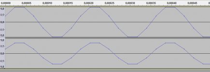
OK this is the output I get when I feed this waveform via a direct S/PDIF stream from the output of my soundblaster into the SRC/DSP. Top waveform is left channel and bottom waveform is the right channel. Output from S/PDIF is at FS.
Attachments

Last edited:
I made the file again this time left 1.08 and right -3dB or 1.08 / sqr(2) = about 0.76 linear. 1.08 linear is about +0.67dBFS so the rigth is about -2.33dBFS.
Asumes that +/-1 top linear corresponds to 0dBFS
And this is the output I get when I feed this waveform via a direct S/PDIF stream from the output of my soundblaster into the SRC/DSP. Top waveform is left channel and bottom waveform is the right channel. Output from S/PDIF is at FS.
Attachments
Last edited:
- Home
- Vendor's Bazaar
- Hi-end DSP based multi-channel integrated Preamp/Crossover/DAC project