Its all in the manual
http://www.diyaudio.com/forums/vend...ow-noise-ldo-regulator-pcb-2.html#post4131518
http://www.diyaudio.com/forums/vend...ow-noise-ldo-regulator-pcb-2.html#post4131518
Hi Ales,
The connection of the sensing pins in case of a dual symmetrical +-power supply is not 100% clear to me.
On the PCB I see SEN.A(-side) and SEN.B(+side)
From the manual: The dual PCB has sensing only for positive voltage
Do I only connect SEN.B(+side) to the load and install a jumper for SEN.A(-side) ?
Regards,
Danny
Hi Ales,
The connection of the sensing pins in case of a dual symmetrical +-power supply is not 100% clear to me.
On the PCB I see SEN.A(-side) and SEN.B(+side)
From the manual: The dual PCB has sensing only for positive voltage
Do I only connect SEN.B(+side) to the load and install a jumper for SEN.A(-side) ?
Regards,
Danny
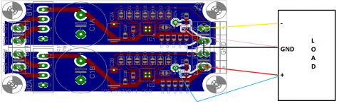
Danny,
you connect SEN. B to the Vo+ and SEN. A to the GND point (+ from A side and - from B side). See attached picture for more clarification.
Best Regards,
Ales
Attachments
Hi guys,
I have single PCBs now available in black color.
Price = 21€ for 1pcs
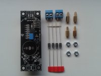
What do you get for the price
Single PCB with smt components soldered on 1pcs
SBYV27 rectifying diode 4pcs
Epcos 1uF/63V PET capacitor 1pcs
Screw PCB connector 2pcs
attached aluminum block 1pcs (works as heatsink or heatbridge)
M3 nuts 4pcs
standoffs 4pcs
Panasonic FR capacitor 1pcs
BR,
Ales
I have single PCBs now available in black color.
Price = 21€ for 1pcs
What do you get for the price
Single PCB with smt components soldered on 1pcs
SBYV27 rectifying diode 4pcs
Epcos 1uF/63V PET capacitor 1pcs
Screw PCB connector 2pcs
attached aluminum block 1pcs (works as heatsink or heatbridge)
M3 nuts 4pcs
standoffs 4pcs
Panasonic FR capacitor 1pcs
BR,
Ales
Attachments
Hi Ales,
In the case I use the sensing connection and due to the design of the chip and the decoupling cap of your pcb : what is according to you the maximum decoupling cap advised in the feet of the terminal load ?
I have a doubt for my DAC chip : can I use 0.1 uF or 1 uF or even more than that ? Does a higher inductance due to a larger leads gap of the local load decoupling cap can waste the very small inductance the X5R pcb caps have ? In another words : would you advise the use of smd caps only for the decoupling RF or local power reserve of the load ?
Sorry if already asked elswhere !
regards
Last edited:
Hi Eldam,
this is the quote from the datasheet: "Optimal noise performance is characterized using a total output capacitor value of 50 μF."
I also tried my headphone amplifier with TPS7A4700 regulators. I made listening test with and without bypass capacitors on the headphone PCB, and local power reserve which is total of (for both channels) 44uF/per rail. I haven't heard any change in sound at all.
If you can use SMD caps or some good small MKP caps such as MKP1837.
Best Regards,
Aleš
Hi Ales,
In the case I use the sensing connection and due to the design of the chip and the decoupling cap of your pcb : what is according to you the maximum decoupling cap advised in the feet of the terminal load ?
I have a doubt for my DAC chip : can I use 0.1 uF or 1 uF or even more than that ? Does a higher inductance due to a larger leads gap of the local load decoupling cap can waste the very small inductance the X5R pcb caps have ? In another words : would you advise the use of smd caps only for the decoupling RF or local power reserve of the load ?
Sorry if already asked elswhere !
regards
Hi Ales,
Yeap I know it, but never really understood if TI just advised it for just the output of the reg or for the whole circuit including the final load !
Ask myself what could be the max value for the local decoupling cap at the feet of the chip/load as I'm not sure to use sensing as I need a ground and a symetric.
Well thanks for your input and experiment about that. Well I imagine as far the inductance stay low (same smd cap size) one can add a little local decoupling for RF around 1 uF maybe. Well, interresting than you say added caps don't change the sound at the end... so no needs to loose time to add some local power reservoir caps near the load/pcb.
For the advised VA of the torroid, many claims it's better not to have too huge VA traffo in relation to the real needs ! So if the load is max 1A due to the max than the reg can feed : the final need is the voltage needed x the current the load ask : e.g. for 7 V and 1 A : 7VA torroid... or 20% more as there is always a loss ?
I understood from the manual the voltage explanation but I would like to stay close to the current cunsimption for the traffo as well !
Hi Ales,
Yeap I know it, but never really understood if TI just advised it for just the output of the reg or for the whole circuit including the final load !
Ask myself what could be the max value for the local decoupling cap at the feet of the chip/load as I'm not sure to use sensing as I need a ground and a symetric.
Well thanks for your input and experiment about that. Well I imagine as far the inductance stay low (same smd cap size) one can add a little local decoupling for RF around 1 uF maybe. Well, interresting than you say added caps don't change the sound at the end... so no needs to loose time to add some local power reservoir caps near the load/pcb.
For the advised VA of the torroid, many claims it's better not to have too huge VA traffo in relation to the real needs ! So if the load is max 1A due to the max than the reg can feed : the final need is the voltage needed x the current the load ask : e.g. for 7 V and 1 A : 7VA torroid... or 20% more as there is always a loss ?
I understood from the manual the voltage explanation but I would like to stay close to the current cunsimption for the traffo as well !
Eldam,
still I can post question on the TI website, regarding output capacitance. I am sure guys there will clear our doubts.
")
On the link below you'll find great explanation how to choose the right transformer. To give you a bit shorter reading, the example you posted (7V DC, 1A) transformer rating should be around 12VA if Vac is 7V. You need to multiply DC current with 1.8 factor, the number you get is AC current.
http://www.audiofaidate.org/it/materiale/20_020_020_001_PowerTransformer_FilterRatings.pdf
One more from Hammond:
http://www.hammondmfg.com/pdf/5c007.pdf
Hi Ales,
great job. How do they perform compared to good LM317 circuits, Salas, tentlab shunts ..etc?
regards
Alex
I had chance to compare them with LM317, TPS7A4700 outperforms them. I haven't had a chance to compare them with other regulators. I would appreciate if someone could post his finding.
BR,
Aleš
I had chance to compare them with LM317, TPS7A4700 outperforms them.
BR,
Aleš
Hi Aleš
Would you please point us the LM317 schematic you're refering to, what measures had been performed, and what kind of load was fed.
Regards,
Phil
Hi Aleš
Would you please point us the LM317 schematic you're refering to, what measures had been performed, and what kind of load was fed.
Regards,
Phil
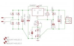
Hi Phil,
please find attached schematic for LM317. I measured both of them on 60Mhz scope, 5V, 100mA, 50ohm load. In both cases I got flat line on the scope. What I was talking about in previous post is that TPS7A sonicaly outperformed LM317, which of course is my subjective opinion.
I tested this on a Pavel Macura BUF634 based amplifier. Input signal was from ODAC with usb isolator, headphones driven were Beyerdynamic T51p.
Best Regards,
Aleš
Attachments
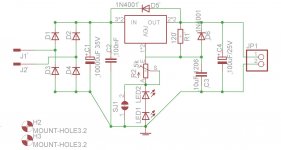
I think your LEDs are the wrong way around.
Jan
Hi Jan,
you're right. This schematic is the right one.
Best Regards,
Aleš
Attachments
Hi Kuni,
depends how you look at it. Dual PCB can handle 1A per voltage rail, so 1A for +12V and 1A for -12V. Price for one is 35€ and with Panasonic FR is 37€.
Best Regards,
Ales
I am interested in dual pcb.
1) I can configure one Vout at 5 V and another part at 9V ? This is possible if I donot want symmetrical supply
2) what parts do I have to solder ?
3) Can you post a picture of the parts that is in the package ?
4) I presume price includes postage by air mail ?
thanks
kp93300
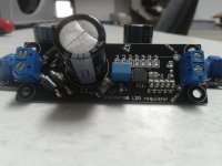
Hi,
please see image of what you receive, though you still can't see Panasonic FR capacitor and small heatsink,but are included in the package. I currently do not offer dual PCBs as one can use two single PCBs and achieve same effect. Price of 21€ is for single PCB + parts, shipping is additional 3€. See first post for additional postage pricing.
Best Regards,
Aleš
Attachments
Hi,
It's possible have 3 pcb + parts?
Marco
You have PM Marco.
BR,
Aleš
- Home
- Vendor's Bazaar
- TPS7A4700 low noise LDO regulator PCB