

An easy mod is adding some capacitance to the clock and the vrefs.
Use a very good regulated power supply for the DAM and also for the USB interface.
If it's a V1 you definitely need to do the lowresmod or the transistormod for the vrefs.
Regarding the "Low Res Mod 499R/0R/0.01R" for REV 1 board, do you leave the 22 uF output capacitor alone or parallel it with 47 uF as in the factory mod?
Cheers!
New Ian ReclockPi
Risking reopening a can of worms, Ian is releasing a new "ReclockPi" that improves I2S LRCK and SCK jitter:
Asynchronous I2S FIFO project, an ultimate weapon to fight the jitter
Asynchronous I2S FIFO project, an ultimate weapon to fight the jitter
I wonder how much difference this would make to stabilize the dam's clocking. Earlier we concluded that the current tracking algorithm is sensitive to input jitter, causing the Si clock frequency to oscillate.
On the one hand I'm thinking: the ReclockPi only brings 1,25 ps improvement as opposed to a FifoPi with a CCHD-957 (6,17 vs. 7,42 ps RMS). And with the Si jitter being a magnitude higher, it might not make much of a dent.
On the other hand you could say it's another 16,8% improvement to something that's been shown to be sensitive on the dam. Visually, the noise seems much lower (this is subject to zoom level of course).
What do you think?
Putting a Kali Reclocker in front of my dam1121 made an audible difference. Surely we'd be talking about diminishing returns here but by how much?
Good point. I asked Ian in the other thread and he responded as follows. I believe him.
tests were from same power supplies, either with or without a ReClockPi.
1. RPi/FifoPi RPi side: A conditionerPi with a 5V USB power adapter
2. FifoPi clean side/ReclockPi: 3.3V voltage rail from a LinearPi with a UcCconditoner 3.3V.
Hi Rodericj,
Berny was referencing to the DAM1021 3.3v onboard regulator that had spikes,
that went away when installing an additional decoupling cap.
Berny was referencing to the DAM1021 3.3v onboard regulator that had spikes,
that went away when installing an additional decoupling cap.
As always, start with clean power first 
Wanting to reduce jitter in a noisy environnement is not easy and will make things sound different... but is it better? Mixed signal environnements are not so easy to deal with, I prefer the Kiss-approach...
Without the simple cap upgrades, I wouldn't do anything else. This is after all (today) the low end of the Soekris-series, but with still quite some potential under the hood if you are really DIY. Safe the money for fifo's and stuff and get a dac upgrade if you really want to buy someting. Just my 2c.
Thanks, Berny!
The 3.3V regulator (SPX1117) does supply the clock as well as the shift registers - right?
So far I only tried to add polymers for decoupling VOut:
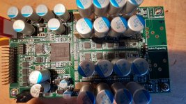
On the one hand directly at the regulator (or rather on top of the adjacent ceramic cap). This does wonders to improve SQ.
On the other hand locally at the shift registers. I tried various configurations (4-12), different caps etc. Never liked it, always got a somewhat muddier output.
I didn't look at it with a scope capable of properly measuring 40 Mhz and beyond though. Was decoupling of VIn necessary to get the improvements you are showing? Then I will try that.
The 3.3V regulator (SPX1117) does supply the clock as well as the shift registers - right?
So far I only tried to add polymers for decoupling VOut:
On the one hand directly at the regulator (or rather on top of the adjacent ceramic cap). This does wonders to improve SQ.
On the other hand locally at the shift registers. I tried various configurations (4-12), different caps etc. Never liked it, always got a somewhat muddier output.
I didn't look at it with a scope capable of properly measuring 40 Mhz and beyond though. Was decoupling of VIn necessary to get the improvements you are showing? Then I will try that.
Last edited:
Also, the balanced output stage in the latest revision is really good - but it doesn't get on-board regulation. You need to feed the DAM1021 very clean low impedance power and use a proper thick (low impedance) ground cable to the PSU of around +/-10V. Too low voltage doesn't sound good, too much will create to much heat and other problems down the road.
Also make sure all the homework in the grounding department is done (PSU directly to chassis, XLR outputs pin 1 to chassis, no other DAM1021 PCB chassis connections.
Also make sure all the homework in the grounding department is done (PSU directly to chassis, XLR outputs pin 1 to chassis, no other DAM1021 PCB chassis connections.
Thanks, Berny!
The 3.3V regulator (SPX1117) does supply the clock as well as the shift registers - right?
No, the shift registers get their supply from the +/- 4V Vref
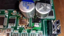
But there is 1 3.3V regulator feeding the mcu, oscillator, isolators, I/O-banks of the FPGA, etc... so allready very noisy to start with. I still use only that same single regulator, but removed the RC feeding the oscillator on the FPGA-side and made a new rcrc filter starting from the regulator tab (also 3.3V) straight to the oscillator. So I use the 'cleaner' side...
Attachments
Last edited:
- Home
- Vendor's Bazaar
- Reference DAC Module - Discrete R-2R Sign Magnitude 24 bit 384 KHz