Datasheet 3v3 regulator: https://nl.mouser.com/datasheet/2/115/ZLDO1117-607727.pdf
"The output of the regulator. A minimum of 4.7µF capacitor (0.05Ω ≤ ESR ≤ 0.5Ω) must be connected from this pin to ground to insure stability. For improved ac load response a larger output capacitor is recommended."
"The output of the regulator. A minimum of 4.7µF capacitor (0.05Ω ≤ ESR ≤ 0.5Ω) must be connected from this pin to ground to insure stability. For improved ac load response a larger output capacitor is recommended."
I've already done the 3v3 upgrades a long time ago, extra clock & 3v3 capacitance, using sparko discretes in that place, bypassed 5V regulators, etc, there isn't much left that can be done with this build that hasn't already been done before or previously recommended. Any jitter in the FPGA is as low it will be without further using some linear job for the 1v8 FPGA power. It might even be worth buffering the 5V leads before going into the series resistor, the rather long power traces aren't exactly what I call great after looking at one of the boards from the underside, I'll be bypassing the 5V at each series transistor input (existing super regulator mod) for the next mod.
Last edited:
Shift registers / buffer. The used 74LVC595 is simple the best for the job. They're faster and have lower output impedance than the HC types.
And I actually measured output impedance on them, not just datasheet specs. And the tiny packages I used on all the next boards are even nicer and have lower wire impedance....
Using discrete mosfet, as some do, is not something I will, to many complications without improvements....
If anything should be improved there, I would need to make a custom chip, basically a power shift register, have already looked into it, but high cost....
And yes, there will at some time come a follow up on the dam1941, using larger FPGA, if I don't decide to drop DIY, I'm a little tired of getting hammered all the time.
And thanks for all the people who enjoy the boards and write nicely, that's why I'm still here, don't really want the few ******** to ruin things for the majority...
Please don't be discouraged Soren. I can only speak for myself but
Its obvious the overwhelming majority is very pleased with your DIY DAM, enjoying it every day, and waiting to whatever next you'll come up with.
+1
Thanks Søren, your DAM DACs have certainly played their part in my enjoyment of life over the last few years
")
May it continue...
Yes, the Soekris DAC is special. Natural and transparent sound, good format compatibility, digital volume control, isolation, serial communication with isolation, custom filters, upgradeable and being able to drive an power amplifier like my nc400 directly without any buffering or i to v stages. Good stuff...
Fedde
Fedde
I am a satisfied dac1541 user. Subscribe to this thread to follow the technology developments. I cringe when I see the overblown hammering.
I might’ve done it a bit more than is usually deserved, but given the forum communication constraints I did slightly differently. If I was unreasonable, I apologize, but there are other reasons that “hammering” might make you cringe.
Yes, that is a wonderful DAC. A modded V1 is my main DAC in the studio. We compared it to mytek and antelope and it is easily on par, better than a RME ufx.
At home i listen with a modded v3. It is a great sounding playground (filters, NOS with external filter etc)
Thanks Soren
At home i listen with a modded v3. It is a great sounding playground (filters, NOS with external filter etc)
Thanks Soren
Here is my DAC
Hello all,
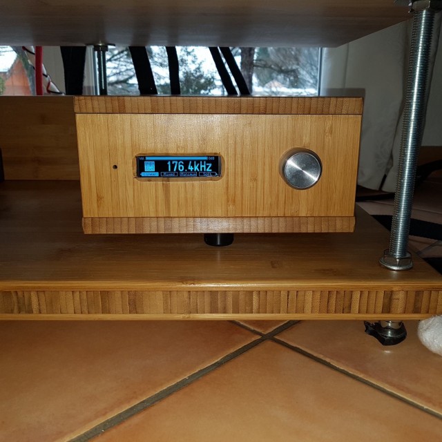
After reading this tread for a while, asking some questions sometimes, it’s time for me to present my DAC based on dam1021 rev5.
I decided to put it in a wood case (bamboo) with the Toroidy Transformer(2x14VAC+6x6VAC) outside the box to avoid 230V perturbations.
DIYINHK power supply LT3045 based, LDOVR LT3045 power regulator for iso and HDMI input from audioGD connected on I2S, also for SPDIF input.
Audiozen board and screen (without transformer), OCC wires.
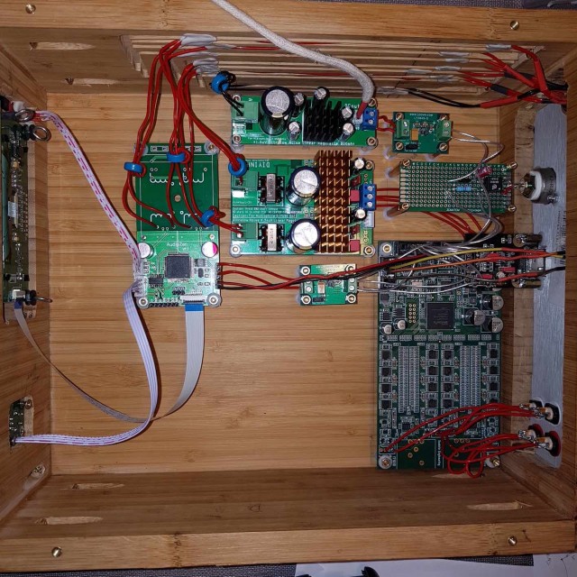
This DAC kicked the audioGD DAC19 big time. It is transparent and sounds very natural. Really enjoy it and would like to thank Soren and the community for the help/advices which helped me a lot in my setup.
Musically,
Faboz
PS: Please stop polluting this tread with out of subject and endless discussions, better to listen music rather than covering pages and pages
Hello all,
After reading this tread for a while, asking some questions sometimes, it’s time for me to present my DAC based on dam1021 rev5.
I decided to put it in a wood case (bamboo) with the Toroidy Transformer(2x14VAC+6x6VAC) outside the box to avoid 230V perturbations.
DIYINHK power supply LT3045 based, LDOVR LT3045 power regulator for iso and HDMI input from audioGD connected on I2S, also for SPDIF input.
Audiozen board and screen (without transformer), OCC wires.
This DAC kicked the audioGD DAC19 big time. It is transparent and sounds very natural. Really enjoy it and would like to thank Soren and the community for the help/advices which helped me a lot in my setup.
Musically,
Faboz
PS: Please stop polluting
this tread with out of subject and endless discussions, better to listen music rather than covering pages and pagesThank you Søren. I too am another very satisfied customer. I have found it extremely satisfying to follow this thread and to do the power supply, vref, and output filter mods. The naturalness of timbre, tone, and overall sound quality is superb.
I am retired and get several hours of very close listening every day. I am genuinely greatful for your products, the time and effort that you put into this thread, and the contributions of the majority of the other posters. Although there are times when a poster or two will take a stridently noxious tone, I hope that you will dismiss that as their passion having simply gotten the best of them.
I would also like to say that I have recently bought one of your 1541 DACs and am very pleased with it. After giving it a 100 hours or so of burn in, and even in stock form, it compares very favorably to my heavily modified 1021. People who aren’t inclined to DIY will get plenty of satisfaction from it just as it is. I am really excited about its prospects with Salas LPSs, vref mods, and polystyrene output caps.
I am using the revision 2 board without any mods along with the Normunds input selector board. The input board is powered separately via the Salas Ref-D board. Now since 4 years or so I was powering the dac with Salas 1.1 and now recently upgraded and built the Salas Ultra BiB 1.3 PSU boards. What I have seen is that the positive board draws around +500mV for the PSU board to be stable against the stated 180mV from the Soekris manual. This doesn't seem to be right for me that a DAC is pulling more than 500mV. Is it normal or do I see an issue as with more than 500mV the psu is stable with +/-12Vdc and I do not want to give any input signals till I am sure that all is right?
thanks
thanks
 thread reopened. Off topic has been split to this thread Musings on soekris Reference Dac Module
 Please keep this thread for questions and answers related to the module.
Discussions on possible improvements, or any other musing should go in the new thread.
Sorry for the delay in getting this cleaned up and re-opened.
Probably this is not the place to be able to denounce the facts, but they have a causal relation with the present device, I have acquired three units of this DAC in the commercial page of Soekris, they are the same as my references, and in that same thread of ideas and good response from the aforementioned device, I promoted among my friends Soekris DAC, the surprise became when after convincing one of my friends,
I acquired a new DAC board. It was mounted on the chosen chassis but some time later. When installing it with a Borberly regulator power supply, I discovered that the negative side rail consumed about 5A, so it burned the fuse and Borberly board regulator,
I proceeded to connect a laboratory source that has a safety limit close to that current of five Amps , and I confirmed that consumption but without prejudice to the sound that was always excellent. I sent an email to Soekris who quickly answered my concern, after measurements I noticed the malfunction of the input diode bridge, he persuaded me to replace it, which I did with limitations given my inability to operate in SMD, after The whole system was sent to its factory, since I considered myself surpassed by the smd technology and the lack of circuit. After four months I received the plate as I had sent it, without working and Soren's response that my welds were horrible and that in his bench the system worked well. I proceeded to express my dissatisfaction and he advised me to take pictures of the system, which I did, and if everything went wrong he would send another replacement board. By the way, another two months passed, I completed the requested procedure and I inquired again his resolution to which he replied that he was not going to give me a new board.
I believe that, from the commercial point of view, any company must reserve a game in order to solve these fortuitous cases since the components of the plate are not measured or individualized. That aside for seriousness is necessary to provide guarantees. That the aforementioned engineer uses the Diyaudio forum to promote his designs, not only to validate among knowledgeable users, but also to generate a profitable economic benefit, given that we do not even get a discount on their acquisition, and finally, besides noting the disability to tell the truth, I consider finally that he has misappropriated my money.
Last edited:
This is clearly a case where you try to do something beyond you capabilities and knowledge. 5A @ 5V is 25W which can't just disappear without smoke somewhere....
I checked your board and found no problem, current draw where it should be and audio played just fine.
The pictures you sent me was pictures of wiring mess, without the board showing, so useless to me.
Sorry, but it is a diy project and you're supposed to at least be able to solder, I can only check the board itself, which I did for free, I can't debug your whole wiring mess and your power supplies.
I have been in business for many years selling diy products, both computer and audio boards, and have learned long time that there are a small percentage of people that are incompetent and blaming the manufacturer for their failures and just impossible to make happy. I never promised to send you another board, that's just a false statement. I wouldn't help you anyway, the board is fine, you just need to fix your power.....
Please direct non technical post to Musings on soekris Reference Dac Module
Last edited:
given my inability to operate in SMD, after The whole system was sent to its factory, since I considered myself surpassed by the smd technology and the lack of circuit. After four months I received the plate as I had sent it, without working and Soren's response that my welds were horrible
This stands a chance of becoming the most unreasonable and absurd complaint of 2019. And also the funniest. But it is hard to be certain with no visible proof. Where are the pics? In high res please
- Home
- Vendor's Bazaar
- Reference DAC Module - Discrete R-2R Sign Magnitude 24 bit 384 KHz