The problem is that the gain is set in dB so you do not get an exact factor 2 this way.
You have a point here, indeed -6 dB is not exactly a factor of two...
(depending on the implementation though. the multiples of 6 dB gains could have been rounded to factors of two to reduce distortion at LSB).
In the meantime, my DAM package has arrived at the local post office. I can pick it up tomorrow...

It's amazing how little I actually know about the DAM DAC... There's just so much hidden in the electrical circuits and components that could affect the performance, completely hidden away from non-majors behind the pretty abstractions... Let alone the fact that we don't really know the full dam1021 schematics...
I found out after studying all 77 pages of Soekris Dam Dac - Tir Na HiFi where Nigel and friends went for (and got VERY far) the ultimate dam1021, destroying a few boards now and then of course.
First of all, correcting my last post, the power regulation on the dam1021 is more likely:
AC/DC -> Bridge rectifier -> PWR A+/-
PWR A+ -> 3.3V Regulators-> Digitals (FPGA, oscillator and microprocessor)
PWR A+ -> 1.2V Regulator -> ?
PWR A+/- -> +/-5V Regulator -> +/- 5V DC -> Op-amps -> 4V vref -> shift registers
PWR A+/- -> Output buffer op-amps
[Probably still missing some but better than last...]
With this, now I can answer my own questions...:
(1) Digital/analog separation in the ground plane, or power in general, is probably not perfect. There is no conclusive evidence but the fact that Nigel and friends believe the vref battery mod was the most significant among all the mods which they A/B tested gives some hint. The mod basically provides independent power supply to the analog circuits (with output buffer already removed...).
(2) One could go all out on battery/externally regulated power supplies for all voltages/major components on-board, as a few did. And replace the 1.2V switch-mode regulator which seems to be noisy by an LDO counterpart... Here's my current idea of a reasonable and accessible mod, if the output buffer is not needed:
i. Supply PWR A+ with 5-7V DC, replace 3.3V regulator with Sparko discrete regulator, wire the VCC on the oscillator directly to the regulator for improved performance.
ii. Replace 1.2V switch-mode regulator with LDO.
iii. Supply ~4V (such as 3.3V with LiFePo4 battery) to shift registers, bypass op-amps. If done with batteries capacitors can be left out, but if done with (here I'm very much not sure...) regulators, supercapcitors might be needed. A possible regulated supply is perhaps Regulated DC -> 4* 4V Sparko Regulators. Sparkos are rated at 3uV ripple, 1.5% voltage precision, and 1A output, which should be enough for the shift registers (??).
iv. Supply future Soekris add-on buffer/headphone amp with the same regulated DC as the Sparkos for the shift registers. Or use an existing buffer kit.
v. (optional?) Swap out certain on-board ceramics for better caps / bridge more caps at places if there's room.
This should provide a higher level of digital/analog separation, better regulated voltage for critical components, and doesn't go as far as using battery supplies. Ideally, this should only require one transformer with two sets of secondaries for digital and analog respectively. one dual-rail linear regulator for analog and one single-rail linear regulator for digital. The enclosure would also have a quality buffer/head-amp built-in.
Does this sound reasonable? If so I might consider doing it next year when I have more time... also ideally after Soren releases the head-amp board so I can stack it with the balanced dam1021's....
This is just a naïve attempt at a decent mod... please offer critiques of any kind!
Happy New Year!
the last board i modded was a revision three which was much better sound than the revision 1
when we started into modding this the boards were cheaper in the rev1 days
consider the risk of ruining boards and the amount of work involved in the part removal
it is probably more suited to experienced compulsive diyers
the rev 4 will be a decent performer as long as its not fed an ac power supply
How good of a power supply do you think is good enough? I'm not talking about pulling the on-board regulators, just feeding the board normally. Seems everyone agrees regulated DC is better than unregulated AC. But there's quite a spectrum on regulated DC, from basic lm317 up to (for example) Salas shunts... Seems that going better than the on-board regs might be well in the overkill territory.
Just wondering what everyone thinks is a good balance between cost+complexity vs diminishing returns.
Just wondering what everyone thinks is a good balance between cost+complexity vs diminishing returns.
How good of a power supply do you think is good enough? I'm not talking about pulling the on-board regulators, just feeding the board normally. Seems everyone agrees regulated DC is better than unregulated AC. But there's quite a spectrum on regulated DC, from basic lm317 up to (for example) Salas shunts... Seems that going better than the on-board regs might be well in the overkill territory.
Just wondering what everyone thinks is a good balance between cost+complexity vs diminishing returns.
because of all the onboard regulation and capacitance there is a certain point where the input ps quality will not matter then they will become the next weakest link
in your case i assume your benchmark will be that tda1387 your working on,
ive done some experiments with that chip too it is indeed very good sounding with a good power supply and good clean i2s signal
you may have to mod the dam 1 a bit more in depth to surpass it
which revision of the dam do u have?
filters matter too, something i havent kept up to speed with
btw i got some of your tda1387 pcbs manufactured
hopefully ill get round to it soon
in your case i assume your benchmark will be that tda1387 your working on,
ive done some experiments with that chip too it is indeed very good sounding with a good power supply and good clean i2s signal
you may have to mod the dam 1 a bit more in depth to surpass it
which revision of the dam do u have?
filters matter too, something i havent kept up to speed with
The goal isn't so much one versus the other, but more just to finish a project that's been in a not-quite-completed state for too long. I've got two rev3 dam1021 boards (for balanced dual-mono). Currently fed i2s from a RPi, powered by the DIYINHK lt3042 regulators, all glued together with Normunds PCB. I've posted pics in this thread if you search for my posts.
I don't think the DIYINHK lt3042 is really ideal for the dam1021, at least not in balanced dual-mono mode: I was having problems with either board randomly loosing sync whenever the mains voltage would sag (e.g. running a paper shredder). Plus the choke gets really hot, making me think the pair of boards pull more current than the regulator was designed to supply.
In short, I'm trying to think of what PSU to use with the pair of dam boards. I have an unbuilt Salas BIB shunt regulator, but I'm thinking that might be overkill... maybe something smaller/simpler will do the trick... hence the question.
Also, the Normunds PCB doesn't allow independent UART control of the two dam1021 boards, it "chains" output from the RPI to the dam boards. That's fine for volume control and filter selection, but won't work for firmware upgrades, changing filter packs or making config changes to one but not the other... so I'm thinking about designing a board similar to the Normunds one, but with a pair of USB to UART chips, or something similar, so that the dam boards can be controlled independently (and can be chained via software). I could also put a power regulator on the board too, if I found something fairly simple (lt3042 is nice, but physically too small for me to solder).
The tda1387 stuff is mostly just me following Abraxalito's lead, and playing with something simple enough for me to fit my head around.
have you tried alternate sources of i2s ?
rpis dont have a great i2s out but it should still be stable
lt3042 arent as bad to solder as yould think, tin one pad then solder pin to it then do the others
if the opamps were removed it would be easier to power too
youll have less noise also
you could parallel the lt3042 either
How good of a power supply do you think is good enough? I'm not talking about pulling the on-board regulators, just feeding the board normally. Seems everyone agrees regulated DC is better than unregulated AC. But there's quite a spectrum on regulated DC, from basic lm317 up to (for example) Salas shunts... Seems that going better than the on-board regs might be well in the overkill territory.
Just wondering what everyone thinks is a good balance between cost+complexity vs diminishing returns.
I have only seen one real comparison between the dam1021 and the dam1121. Post 288 of the link below. The user states that despite the differences his ear couldn't discern a difference. Plus the dam1021 has the easy to implement AudioZen OLED board (which was my Christmas gift).
Building with the Soekris dam1121
I'm sure the dam1021 has very good regulation and the differences might not even be audible. That being said some of the Salas regulators are known as the best for a reason.
Søren's Audiophile line is doing well and has very good measurements from what I have seen. The DIY dam1021 line is a very good all in one solution which is easy to build for any DIY'er.
Sadly I'm not sure the OEM dam1121 is doing as well. It's just too cost prohibitive especially stateside. For a fully balanced build it would cost $569 for the .02% version and $804.48 for the .01% + international shipping + 6 power supplies. Honestly I think Søren would be surprised how well a DIY line dam1121 with op-amp balanced outputs would sell. Added bonus if it has analog control too (but not necessary).
if the opamps were removed it would be easier to power too
youll have less noise also
you could parallel the lt3042 either
I have rev. 2 board that has 2 opamps per channel, so I remove both, right? Salas PSU is waiting for better days, don't have enough time to try it.
So, if I remove both opamps, how much voltage is enough just for raw outputs?
Regards
I have rev. 2 board that has 2 opamps per channel, so I remove both, right? Salas PSU is waiting for better days, don't have enough time to try it.
So, if I remove both opamps, how much voltage is enough just for raw outputs?
Regards
theres a 5v and -5v reg on there pre regulation for v-ref
just look up their data sheet for the minimum voltage its probably around +/-7v
mine runs with +/- 3.3v and 1.2v as ive replaced all onboard regulation and removed or replaced most caps
I don't think the DIYINHK lt3042 is really ideal for the dam1021, at least not in balanced dual-mono mode: I was having problems with either board randomly loosing sync whenever the mains voltage would sag (e.g. running a paper shredder). Plus the choke gets really hot, making me think the pair of boards pull more current than the regulator was designed to supply.
I use 2 x DIYINHK LT3042 baords with a dual-mono DAM1021 and 12V secondaries to keep temps in check. (A regulator board for each DAM...)
Someone on a Dutch forum said in August that Soekris is working on a native board for the Raspberry Pi.
What have you heard about this, is there any truth to this?
I am planning a Rasptouch enclosure and am thinking of either a SPDIF out (digione) or a version with an internal DAC board so RCA out. [The sigmadeltas that are standard with Rasptouch have no charm for me, too much 'presence'/slight accentuation of the mids, too dynamic.]
- One option is R2R. And if Soekris has such a board with its standard isolation, reclocking, buffering I would be very happy.
- I like the neutral to soft/slightly laid back sound of PCM1704 (my board broke down )
triode_al, see post #6397: http://www.diyaudio.com/forums/vend...magnitude-24-bit-384-khz-640.html#post5059536
The problem is that the gain is set in dB so you do not get an exact factor 2 this way.
For listening it probably does not matter, but for some measurements control of the actually set bits can matter.
Would also be very interested in seeing it implemented to get bit-exactness at some volume steps.
Also, is there an optimum volume setting in the dam1021? It seems 0db has much more higher order harmonic distortions than -60db, is there a volume setting that corresponds to exactly 16/24 bits used? I'm currently using foobar2000 and it also seems to have a digital volume control. Is there a reason to bypass it and stick to 0db I2S inputs?
Thanks!
... is there a volume setting that corresponds to exactly 16/24 bits used? ...
16/24? For non-compromized MSB (LSB will be lost!!), a shift right operation on every word (MSB....LSB) shall be done. One step right means 50% or 6,02 dB. The bit depth of the payload is of no importance. I remain confident that to do this with the least impact, dither is required.
//
Last edited:
Second build
------------- Build stuff -----------------
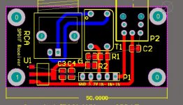
I finally got back to the build after a short New Years trip. Stacked the two dam1021's and paralleled the spdif/I2S inputs with extended (~21mm) headers. It couldn't get a lock at first, then I realized my homemade SPDIF input board is probably drawing too much current from the SK Lite 3.3v reg, so much as to cause the voltage to drop to 0.8v. I then removed the 3.3v power to the SPDIF board and the voltage came back to ~3.6v. I posted the schematics and pcb design of the SPDIF input board if anyone is interested in it. The board was designed to take 3.3v and regulate it onboard to 1.2v for the coax. The dimension is 50*25mm - a rather small footprint that was supposed to fit nicely in my chassis.
However, only the top board was able to get a lock in the first few minutes even after the power to SPDIF board was cut. I suppose it was because the S22 clone was still warming up and the voltage at the oscillator or whatever was causing the problem wasn't quite stable enough. After some time both boards were able to get signal lock without any problem.
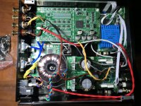
My enclosure is 215*228*70mm so everything was really tight on paper. And it indeed took much thought just to fit everything together. Here's some pics to the setup. I'm using a 35w 12v toroidal and S22 clone (HP-X) at 9V DC output to power the 1021s. The USB board is an amanero clone. SK Lite is used for control and powering the ISO section (and the would-be SPDIF input board...) with an independent secondary.
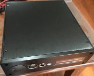
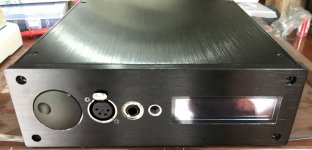
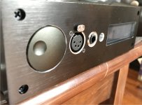
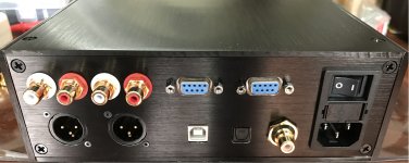
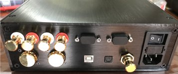
Raw outputs are connected to 3-pin XLRs and RCAs just for convenience, and buffered outputs are wired to 6.3mm SE and 4-pin XLR on the front panel for headphone use. I had room on the back panel for two RS232 ports so I did, straight to the dam1021s - the most reliable and easiest way imo.
I had a small ground wire collector in my first build but there weren't really that many wires in the star ground (only 2 actually), so I got rid of it. Now the ground is just connected to the safety earth with a bridge rectifier in between.
I also attached my front and back panel drawings. I used fusion360 for the front panel but it seems STP format is more universal..
------------- Mod stuff ------------------
Many thanks to randytsuch and nige2000 for the additional reports on SQ gains with the battery mod. If only rev1 was tested to improve with battery supplies in vref, it might be explained away by the insufficient vref back then. I do have the ISO powered by an separate transformer and low noise regulator on the SK Lite so I guess I'm okay there.
Perhaps it's possible that the onboard regs and filters do indeed work well enough in the presence of "clean" DC supply, and that no additional mods are necessary or even could produce better subjective sound, as Soren seems to have always insisted. I'm not an EE person so I guess this is as much assertion as I could make with some confidence, and until Soren reveal more about the schematics or there is reliable information that a mod leads to better SQ, I'll just stick to the unmodded 1021s for now...
Much of the discussion on what to mod and why Soren did what he did seems to come down to the design goals and individual view on purchasing. Although Soren said outright that he is building the "best dac on the planet", such a claim cannot be interpreted to its extreme. In fact, I think maybe what he meant is something along the lines of "the best dac with a cost-effective approach in mind (as opposed to Totaldac/MSB's nonexistent budget ) and perhaps with a relatively compact size".
This is also reflected in Soren's design choices in his commercial products. Dam1541 is very compact, but at the cost of using switch-mode power supplies, which is not usually the to-go for high-end products. It corroborate the point that perhaps compactness is a meaningful dimension in the Soekris dacs, as well as cost-effectiveness as I'll discuss later. This effectively means that the performance will not be the "absolute" best, as I have admittedly sometimes suffered from imagining.
What most of us really care about is perhaps cost-effectiveness - based on our purchasing power and the goods available in the world, find a general threshold of cost-effectiveness, lower than which lies the numerous luxuries that we could not rationally purchase, as much as its positive but near non-existent marginal value to us maybe. We want to "eliminate the weakest link in the system", which is likely the most cost-effective approach, until perhaps it hits our budget, becomes too complex, time-consuming and tedious, or reaches a true engineering obstacle that cannot be solved with our current technology, no matter how much money we are willing to throw at it. The last item, I think, is the most interesting concept in this long section of my post. Although Soren did not explain his reasoning explicitly, there's another possible interpretation to his claim of "best dac on the planet" that might be meaningful to those of us pursuing the "cost-effective approach", which I did not take into account in my rebuttal of the "absolute best".
Again I’m not an insider in this area so please argue against if you think I’m wrong. The point here is that perhaps this discrete R-2R sign magnitude technology dac is most limited by how accurate and thermally stable we can make our resistors. In other words, without improvements in the resistors, anything else done to a rev4 board, and I’m speculating here, will have a much much lower cost-effectiveness – something that Soren is clearly against.
However, as I went back to the first pages of this thread, I became temporarily confused at how Soren seems to be aiming at a “low cost discrete dac” from the get-go. Soren did not provide the option of matching resistors or consider using better Z-foil resistors, when more accurate resistors is indeed the most important part of building a great discrete R-2R dac. After I slept on it, I realized the central position cost-effectiveness occupies in Soren’s designs, and perhaps should occupy in every good professional engineer. So far, my view has gone from brushing-off Soren’s pursuit of the best, to admitting that there maybe something in his claim in the insurmountable technical challenges that he may have faced. I now believe that Soren did indeed set out to build “the best”, but meaning something quite subtle – the best performance under a very specific cost-effectiveness threshold that he had in mind. Granted Totaldac probably beats the dam dac, but it has “the price of a car”. Granted good S-D dacs can be had for cheaper (or way more expensive…), but Soren believes that discrete R-2R tech is better than “any S-D dac”.
Therefore, the dam dac is supposed to hold a special place in the world of dacs in terms of cost-effectiveness – worse than the chips on your motherboard (not that it matters because we have a looser cost-effective threshold); worse than very cheap sigma-delta dacs (again, not that it matters because we have a looser cost-effective threshold); better than all S-D dacs priced higher than, say, 90% of the dam1021 solution, depending on how much you agree with Soren’s claim that R-2R when implemented well is superior to any D-S (I can at least agree that D-S made a lot of compromises to how the analog signal is produced, maybe too much to be considered a good candidate for the ultimate dac technology, as perfect as it might sound to the human ear.); better than all decent discrete R-2R dacs currently available because of its superior cost-effectiveness; and better than PCM1704 solutions because they no longer exist.
To me, the elegance in the engineering (R2R is a clear winner here) and objective measurements holds just as much if not more value than subjective enjoyment and the ability to be better immersed in the musical arts. I imagined earlier that the core r2r tech is the absolute best possible, which would hold much value for me as a source of inspiration to a perfectionist (I’d like to think of its positive connotations here ), but alas, it’s not. Still, this is an excellent diy project for those of us who believe in or appreciate R-2R, and have a similar cost-effectiveness threshold as Soren.
In conclusion, to consider the cost-effectiveness of an approach, we should perhaps first consider our own thresholds, then appraise the cost-effectiveness of the particular approach. In this case, rationally speaking, modding seems to be a way of saying that we have a looser constraint of cost-effectiveness than Soren, provided that he didn’t make any mistakes as appears to be the case in rev4. However, going back to how important the core R-2R part of the dac is, and how it consists of 216 0603 delicate resistors soldered in place already, perhaps modding will not be as useful as we hope it would be and we’ll just have to stick to Soren’s idea of the “most cost-effective approach”. That said, it is perfectly fine imo to mod just for learning or the fun of it.
Hope this is somewhat useful to other folks as it was to myself in clarifying how to mod and what cost-effectiveness means here. Matt_garman if you have read this far I wish you the best of luck in finding the perfect PSU that matches the dam1021 cost-effectiveness wise, and I’ll just happily stay with the S22 that you recommended to me as it seems to have good measurements, reviews and has a clone (HP-X by ZeroZone in China) that is just the right physical size for my current build.
---------------------- Sad stuff -------------------------
Unfortunately, in the process of moving the system, which didn’t make much use of connectors and has many soldered connections...., I broke the legs of a MOSFET on the PSU. When I tried to solder it back on, I must have burnt it as the PSU is sort of shorting and not working now… For many reasons I will have to hold off repair plans (as easy as it probably is..) until the end of year, but I’m glad to have gone this far. Many many thanks again to everyone here who helped clear things up for me and to those who contributed to this project, besides Soren of course, but he’s probably made enough money out of this “diy project” so I guess it’s fine to be a bit restrained in my gratitude
Also, I might not have as much free time as I’d like now to share my build in full detail which could be of help to those planning a build but don’t want to do everything all over again on his own. To be honest I don’t even know if my build is done right as everything is so tightly squeezed together as to perhaps cause EMI problems. Do I need to shield the toroidal transformers, or it is generally understood to be fine without, especially in a balanced setup? I would prefer to measure the EMI but good measurements can be prohibitively expensive…
Anyway, hope this helps!
P.S. The circle left open besides the OLED panel is supposed to have a black IR pass filter glued on top. Would've looked better if finished!
P.P.S The PcbDoc of the SPDIF board is 6mb and could not be uploaded, I'll just include a screenshot for now... would love to hear some feedbacks on it as it's not working well have a 3.3V 200ma regulated supply feeding this and two dam1021 isolators, is there enough power to go around?.. Thanks!
------------- Build stuff -----------------
I finally got back to the build after a short New Years trip. Stacked the two dam1021's and paralleled the spdif/I2S inputs with extended (~21mm) headers. It couldn't get a lock at first, then I realized my homemade SPDIF input board is probably drawing too much current from the SK Lite 3.3v reg, so much as to cause the voltage to drop to 0.8v. I then removed the 3.3v power to the SPDIF board and the voltage came back to ~3.6v. I posted the schematics and pcb design of the SPDIF input board if anyone is interested in it. The board was designed to take 3.3v and regulate it onboard to 1.2v for the coax. The dimension is 50*25mm - a rather small footprint that was supposed to fit nicely in my chassis.
However, only the top board was able to get a lock in the first few minutes even after the power to SPDIF board was cut. I suppose it was because the S22 clone was still warming up and the voltage at the oscillator or whatever was causing the problem wasn't quite stable enough. After some time both boards were able to get signal lock without any problem.
My enclosure is 215*228*70mm so everything was really tight on paper. And it indeed took much thought just to fit everything together. Here's some pics to the setup. I'm using a 35w 12v toroidal and S22 clone (HP-X) at 9V DC output to power the 1021s. The USB board is an amanero clone. SK Lite is used for control and powering the ISO section (and the would-be SPDIF input board...) with an independent secondary.
Raw outputs are connected to 3-pin XLRs and RCAs just for convenience, and buffered outputs are wired to 6.3mm SE and 4-pin XLR on the front panel for headphone use. I had room on the back panel for two RS232 ports so I did, straight to the dam1021s - the most reliable and easiest way imo.
I had a small ground wire collector in my first build but there weren't really that many wires in the star ground (only 2 actually), so I got rid of it. Now the ground is just connected to the safety earth with a bridge rectifier in between.
I also attached my front and back panel drawings. I used fusion360 for the front panel but it seems STP format is more universal..
------------- Mod stuff ------------------
Many thanks to randytsuch and nige2000 for the additional reports on SQ gains with the battery mod. If only rev1 was tested to improve with battery supplies in vref, it might be explained away by the insufficient vref back then. I do have the ISO powered by an separate transformer and low noise regulator on the SK Lite so I guess I'm okay there.
Perhaps it's possible that the onboard regs and filters do indeed work well enough in the presence of "clean" DC supply, and that no additional mods are necessary or even could produce better subjective sound, as Soren seems to have always insisted. I'm not an EE person so I guess this is as much assertion as I could make with some confidence, and until Soren reveal more about the schematics or there is reliable information that a mod leads to better SQ, I'll just stick to the unmodded 1021s for now...
Much of the discussion on what to mod and why Soren did what he did seems to come down to the design goals and individual view on purchasing. Although Soren said outright that he is building the "best dac on the planet", such a claim cannot be interpreted to its extreme. In fact, I think maybe what he meant is something along the lines of "the best dac with a cost-effective approach in mind (as opposed to Totaldac/MSB's nonexistent budget
) and perhaps with a relatively compact size". This is also reflected in Soren's design choices in his commercial products. Dam1541 is very compact, but at the cost of using switch-mode power supplies, which is not usually the to-go for high-end products. It corroborate the point that perhaps compactness is a meaningful dimension in the Soekris dacs, as well as cost-effectiveness as I'll discuss later. This effectively means that the performance will not be the "absolute" best, as I have admittedly sometimes suffered from imagining.
What most of us really care about is perhaps cost-effectiveness - based on our purchasing power and the goods available in the world, find a general threshold of cost-effectiveness, lower than which lies the numerous luxuries that we could not rationally purchase, as much as its positive but near non-existent marginal value to us maybe. We want to "eliminate the weakest link in the system", which is likely the most cost-effective approach, until perhaps it hits our budget, becomes too complex, time-consuming and tedious, or reaches a true engineering obstacle that cannot be solved with our current technology, no matter how much money we are willing to throw at it. The last item, I think, is the most interesting concept in this long section of my post. Although Soren did not explain his reasoning explicitly, there's another possible interpretation to his claim of "best dac on the planet" that might be meaningful to those of us pursuing the "cost-effective approach", which I did not take into account in my rebuttal of the "absolute best".
Again I’m not an insider in this area so please argue against if you think I’m wrong. The point here is that perhaps this discrete R-2R sign magnitude technology dac is most limited by how accurate and thermally stable we can make our resistors. In other words, without improvements in the resistors, anything else done to a rev4 board, and I’m speculating here, will have a much much lower cost-effectiveness – something that Soren is clearly against.
However, as I went back to the first pages of this thread, I became temporarily confused at how Soren seems to be aiming at a “low cost discrete dac” from the get-go. Soren did not provide the option of matching resistors or consider using better Z-foil resistors, when more accurate resistors is indeed the most important part of building a great discrete R-2R dac. After I slept on it, I realized the central position cost-effectiveness occupies in Soren’s designs, and perhaps should occupy in every good professional engineer. So far, my view has gone from brushing-off Soren’s pursuit of the best, to admitting that there maybe something in his claim in the insurmountable technical challenges that he may have faced. I now believe that Soren did indeed set out to build “the best”, but meaning something quite subtle – the best performance under a very specific cost-effectiveness threshold that he had in mind. Granted Totaldac probably beats the dam dac, but it has “the price of a car”. Granted good S-D dacs can be had for cheaper (or way more expensive…), but Soren believes that discrete R-2R tech is better than “any S-D dac”.
Therefore, the dam dac is supposed to hold a special place in the world of dacs in terms of cost-effectiveness – worse than the chips on your motherboard (not that it matters because we have a looser cost-effective threshold); worse than very cheap sigma-delta dacs (again, not that it matters because we have a looser cost-effective threshold); better than all S-D dacs priced higher than, say, 90% of the dam1021 solution, depending on how much you agree with Soren’s claim that R-2R when implemented well is superior to any D-S (I can at least agree that D-S made a lot of compromises to how the analog signal is produced, maybe too much to be considered a good candidate for the ultimate dac technology, as perfect as it might sound to the human ear.); better than all decent discrete R-2R dacs currently available because of its superior cost-effectiveness; and better than PCM1704 solutions because they no longer exist.
To me, the elegance in the engineering (R2R is a clear winner here) and objective measurements holds just as much if not more value than subjective enjoyment and the ability to be better immersed in the musical arts. I imagined earlier that the core r2r tech is the absolute best possible, which would hold much value for me as a source of inspiration to a perfectionist (I’d like to think of its positive connotations here
), but alas, it’s not. Still, this is an excellent diy project for those of us who believe in or appreciate R-2R, and have a similar cost-effectiveness threshold as Soren.In conclusion, to consider the cost-effectiveness of an approach, we should perhaps first consider our own thresholds, then appraise the cost-effectiveness of the particular approach. In this case, rationally speaking, modding seems to be a way of saying that we have a looser constraint of cost-effectiveness than Soren, provided that he didn’t make any mistakes as appears to be the case in rev4. However, going back to how important the core R-2R part of the dac is, and how it consists of 216 0603 delicate resistors soldered in place already, perhaps modding will not be as useful as we hope it would be and we’ll just have to stick to Soren’s idea of the “most cost-effective approach”. That said, it is perfectly fine imo to mod just for learning or the fun of it.
Hope this is somewhat useful to other folks as it was to myself in clarifying how to mod and what cost-effectiveness means here. Matt_garman if you have read this far I wish you the best of luck in finding the perfect PSU that matches the dam1021 cost-effectiveness wise, and I’ll just happily stay with the S22 that you recommended to me as it seems to have good measurements, reviews and has a clone (HP-X by ZeroZone in China) that is just the right physical size for my current build.
---------------------- Sad stuff -------------------------
Unfortunately, in the process of moving the system, which didn’t make much use of connectors and has many soldered connections...., I broke the legs of a MOSFET on the PSU. When I tried to solder it back on, I must have burnt it as the PSU is sort of shorting and not working now… For many reasons I will have to hold off repair plans (as easy as it probably is..) until the end of year, but I’m glad to have gone this far. Many many thanks again to everyone here who helped clear things up for me and to those who contributed to this project, besides Soren of course, but he’s probably made enough money out of this “diy project” so I guess it’s fine to be a bit restrained in my gratitude
Also, I might not have as much free time as I’d like now to share my build in full detail which could be of help to those planning a build but don’t want to do everything all over again on his own. To be honest I don’t even know if my build is done right as everything is so tightly squeezed together as to perhaps cause EMI problems. Do I need to shield the toroidal transformers, or it is generally understood to be fine without, especially in a balanced setup? I would prefer to measure the EMI but good measurements can be prohibitively expensive…
Anyway, hope this helps!
P.S. The circle left open besides the OLED panel is supposed to have a black IR pass filter glued on top. Would've looked better if finished!
P.P.S The PcbDoc of the SPDIF board is 6mb and could not be uploaded, I'll just include a screenshot for now... would love to hear some feedbacks on it as it's not working well
have a 3.3V 200ma regulated supply feeding this and two dam1021 isolators, is there enough power to go around?.. Thanks!Attachments
-
SPDIF_Input_Board_Schematic.zip7.5 KB · Views: 49
-
 SPDIF_Receiver_PCB.jpg81 KB · Views: 341
 -
 Build_2_Compressed.jpg262.5 KB · Views: 350
 -
 Top_View.jpg944.5 KB · Views: 344
 -
 Front_Panel.jpg794.2 KB · Views: 330
 -
 Front_Panel_Closeup.jpg908.7 KB · Views: 328
 -
 Back_Panel.jpg945.2 KB · Views: 134
 -
 Back_Panel_Capped.jpg879.7 KB · Views: 142
 -
Front_Back_Panels.zip56 KB · Views: 41
16/24? For non-compromized MSB (LSB will be lost!!), a shift right operation on every word (MSB....LSB) shall be done. One step right means 50% or 6,02 dB. The bit depth of the payload is of no importance. I remain confident that to do this with the least impact, dither is required.
//
Thanks that clarifies things! Hope this useful feature get included in the firmware at some point
It will complicate things and "shift right" only work at -6, -12, -18 ... etc levels. And everything between needs to be done in an other way. Still, it would be a nice gesture Also actually useful if you for some reason like to set the DAC in a permanently attenuated mode like I do - appr. 18 dB. Dither is needed at all levels.
//
Also actually useful if you for some reason like to set the DAC in a permanently attenuated mode like I do - appr. 18 dB. Dither is needed at all levels.//
Last edited:
- Home
- Vendor's Bazaar
- Reference DAC Module - Discrete R-2R Sign Magnitude 24 bit 384 KHz