Flip-flops are cheap, clocks are expensive.... One good 50-500 euro.
I bought NZ2520 45.xxx/49.xxx MHz for 8$ each. They are as good as Crystek.
So i don't see any trouble with better clocks.
Also remember Sören doesn't pay what we pay for components, since he doesn't use mouser/digikey etc. So i don't see any trouble here...
-100 dBC @ 10 hz?
//
Don't remember where i saw one for the 4X.XXX MHz, but acko posted measurements for the 9X.XXX MHz ones recently.
Check here - http://www.diyaudio.com/forums/group-buys/227502-amanero-isolator-reclocker-gb-27.html#post4133815
-95. ... Its ok")
4x MHz range should have lower phase noise then 9x MHz. Also i don't think more than 22/24 will be needed for this dac - which would mean even better figures.
..
high quality flip-flop be inserted right after the FPGA. Such would then leave no doubt about what the final jitter into the R2R network would be. ..
This will be great but remember this is multi-bit output and all these lines need to be re-clocked - more space required for the FFs. Maybe even move the isolation from input to after the FPGA. Also, no point having super-duper FFs if it is going to be driven by less than favourable clock.
Excuse me for back-tracking the thread a little but I would like to check I’m not misunderstanding something…
Acko, I don’t disagree with the points you have made about the FIFO/reclocker inherent in the Soekris R2R DAC delivering consistent results through the DAC and it was the same functions on your SO3 board that I was suggesting would therefore be superfluous if used with the Soekris R2R DAC, however, my suggestion for using your SO3 in front of the Soekris DAC was specifically in the context of using a Beaglebone Black (BBB) as the transport.
My understanding is that, because of the limitations of the BBB’s onboard clock it will resample all 44.1KHz family data to a 48KHz related rates – this may be audible – and, if the BBB is connected directly to the R2R DAC inputs the DAC will process the data at 48KHz, i.e. it will process the previously compromised data ‘as is’.
I was suggesting the use of an SO3 between the BBB and R2R DAC only as a means of keeping the native sample rates of the data processed through the BBB (in conjunction with the miero driver obviously) - are you saying this is wrong?
Thanks
Ray
Apologies, I missed this point in my earlier post but are absolutely right.
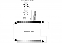
The S03 will effectively serves as a clock module for BBB in this case. But then again you could use something simpler as shown to connect directly to Soren's DAC. Based on my previous post these clocks need not be top-end types as the Si514 on Soren's DAC determines the final outcome. If fact for BBB you can use its internal 24.576MHz and use a single external 22.5792MHz to make it even simpler
I will roll out the next version of BBB-UFL adapters with clocks options on board accordingly
Attachments
I bought NZ2520 45.xxx/49.xxx MHz for 8$ each. They are as good as Crystek.
So i don't see any trouble with better clocks.
Also remember Sören doesn't pay what we pay for components, since he doesn't use mouser/digikey etc. So i don't see any trouble here...
Based on Soren's explanation his FIFO engine requires a programmable oscillator that is dynamically adjusted to manage a skinny buffer. This may preclude the use of native cut fixed oscillators of better performance and therefore to disadvantage.
I guess the next best option is to use Si570 that has better jitter performance. Soren has indicated against this choice before based on power consumption. Other than that I do not see other types of better programmable oscillators, so unless there is a radical overhaul of the FIFO mechanism the options for improvements this way are very limited.
Last edited:
I've read great reviews of DAC's with the DAC chip itself driven directly from a standard SPDIF receiver....
I've read great reviews of DAC's with harmonics like mine but at higher levels....
I've read great reviews of DAC's with cheap opamp's as output buffers....
I don't look at a single parameter as the holy grail, but do my best to pay attention to everything and make an affordable reference DAC. So I stand behind my design decisions, maybe after you all get the chance to play with one there might be enough useful feedback to make a successor sometime....
And its too late anyway, all parts for the first production series are at the contract manufacturer, for assembly to be done this coming week....
LOL!
I DO like the idea of 'gilding the lily' with a better clock or reclocking scheme, but not nearly as much as I like hearing the magic words in those dulcet engineering tones '...all parts for the first production series are at the contract manufacturer, for assembly to be done this coming week....''.
Soren, you just made my weekend!!!!
Greg in Mississippi
That's great news Soren! I know we all are looking forward to trying your thoughtful and affordable design.
I just hope that I made my reservation in time to be in the first run.
Please do be sure to e-mail everybody to let each of us know where we sit in the queue.
Thanks!
Alex.
I just hope that I made my reservation in time to be in the first run.
Please do be sure to e-mail everybody to let each of us know where we sit in the queue.
Thanks!
Alex.
I've read great reviews of DAC's with the DAC chip itself driven directly from a standard SPDIF receiver....
I've read great reviews of DAC's with harmonics like mine but at higher levels....
I've read great reviews of DAC's with cheap opamp's as output buffers....
I don't look at a single parameter as the holy grail, but do my best to pay attention to everything and make an affordable reference DAC. So I stand behind my design decisions, maybe after you all get the chance to play with one there might be enough useful feedback to make a successor sometime....
And its too late anyway, all parts for the first production series are at the contract manufacturer, for assembly to be done this coming week....
Great news
Is there any more detail available on interfacing with the volume control for the DAC. I'd ultimately like to have input switching and volume selectable by remote control.
Hi Soekris,
Impressive work you did, thank you for sharing.
Sorry if already asked, it's ok for me if members have answers not to waste the time of Soren as he is very busy in this final launch phase :
1-Is it only I2S or as the spidf is bit perfect did you allow also foot prints for BNC plugs on the pcb
2- Is there a possibility with a vias or connector to avoid final oaps and hacking the signal on a daugther board buffer ? It is a voltage output before the first oap (no I/V conversion on a R2R ?) ?
If yes are you not afraid this last " relativly simple" last stage affect the outstanding development maid before on the digital stage ?
3- Are the actual oaps local decoupling cap are X7R ? Are you not afraid of the fhz stability of the class 2 ceramic here in the ears fhz range. Ok inductance is at its best but did you benchmark on your prototype higher foot prints smt caps (aluminium cans, pps) for those oaps? Does it change the subjective result in an ABX test ?
4- Same question for the main decoupling caps: you choosed the best in relation to the datasheet but have you tested some others caps with maybe higher ESR but which can give a total difference of sound (for the best like the worst !) ?
Or does it no affect the sound ? I understand the smt can main caps choice because of the manufacturing, but did you think of a non populated board version for those board with holes to try non smt caps ? Some polymers with leads and 2 mm pitch have 5 mohms ESR (not very often with higher voltage than 6.3 V unluckily : Nichicon PLE or FPcap R5 series, etc). Or does the main caps in the prototypes maids didn't change the subjective sound quality at all when you checked with ears ?
Sorry for two cents or if you feel it's off topic as I'm not technician at all !
Wait with impatience the first batch as I'm on the first list...just a little frightened because the ceramics caps on the final oaps in relation to the outstanding development maid before it....
Last edited:
Reclocking after FPGA and better close in phase noise will probably be needed...
//
Absolutely. And no variable, digital PLL clocks... ime these don't sound good at all... Alas, adjustable clocks seem inherent of this concept...
Wait with impatience the first batch as I'm on the first list...just a little frightened because the ceramics caps on the final oaps in relation to the outstanding development maid before it....
Earlier in the thread, it was revealed that there is a mechanism to bypass the final op-amp section, and use whatever output option you are wanting to use.
Perhaps later versions of this DAC will have more "tweaking" options. The board would not be as small, and of course whenever you change one thing, you just want to change more.
A question though for Søren, especially now that the board is in/nearing production, is : do you have a name for your project DAC yet?
You don't need to bypass anything, there is raw output straight from the resistor network, it is pure resistive load which can drive input stage of any amp/preamp with high input impedance and high sensitivity.
- Home
- Vendor's Bazaar
- Reference DAC Module - Discrete R-2R Sign Magnitude 24 bit 384 KHz