0.01% version:
Was originally planning for the 0.05% resistor version first, due to leadtime of parts. Will now also put priority to get 0.02% resistor version at the same time. I personally don't see the big need for the 0.01% resistor version, the sign magnitude architecture lower the requirement for resistor precision. But I will look into it, has calculated the 0.01% resistor version to USD 350. And all pricing is for complete and tested board, without connectors mounted so you have flexibility.
Thanks, looks like the 0.02% version might be the sober choice then! This way I can order two boards and let the true DIY spirit play with one
") Anyway, if most people prefer the more expensive version then be it but only if there is something to be gained, you know your design better than anyone.
Anyway, if most people prefer the more expensive version then be it but only if there is something to be gained, you know your design better than anyone. I would also like to mention that DSD is a very very interesting thing and I do hope to have a device that can do it all and sound like the Total Dac but let's not overload that beautiful project with too many wishes, I need an active filter and a DSD device too but it is more important that it makes good pancakes and Mojito
what would one need to use in an active, 8 channel system?
The boards are stereo, so 4 pcs.
Hmm, i dont see any capacitive compensation of the R2R network. Is it not needed here?
Don't really understand what you mean there, but no need for anything, there is just a simple capacitor at the output of the DAC's resistor chain, making a 270 Khz Bessel low pas filter.
It's a DAC module based on a discrete R-2R sign magnitude DAC design, with FPGA based reclocking and custom digital filters...
Ok, the temperature coefficients on those resistors are very important! Not only telling the 0.0x% precisions!
.. with 28 bit resolution so there is headroom, oversampling up to maybe 3.072 Mhz.
Nice would be some spline oversampling as WADIA used..
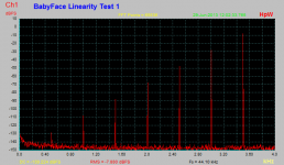
Low level linearity may done as I did using a fast test setup...
See picture
Attachments
Ok, the temperature coefficients on those resistors are very important! Not only telling the 0.0x% precisions!
I have spent quote some time selecting the right resistors, trying to get as much info on them as possible (not that it's easy). Turns out that the temp coeff are mostly not linear, but parabolic towards temperature extremes. So as the board is designed to operate from 0-50 deg celcius, I decided to use:
0.05% - 25 ppm/C
0.02% - 10 ppm/C
0.01% - 5 ppm/C
Nice would be some spline oversampling as WADIA used..
I'm very interested in ideas on oversampling/filtering, having not done that much research yet, but would need more details....
Low level linearity may done as I did using a fast test setup...
I also did a -120db FFT, looked perfect, but as my test equipment consist of a EMU-0404 and I expect my DAC to be better than the EMU, I can't really use that as I'm mostly measing the EMU.... And in principle, a sign magnitude DAC should have perfect level linearity.
...I'm very interested in ideas on oversampling/filtering, having not done that much research yet, but would need more details....
In the past, an FPGA based FIR filter would push the designer toward an hardware compact filter implementation, which has typically been an half-band digital filter. Of course, an half-band filter compromises filter band-edge performance (being down only 6dB at the Nyquist frequency) for hardware compactness.
If hardware resources inside that Spartan 6 FPGA will permit, I suggest implementing an non-half-band filter which is fully in to the filter's stop-band at CD's 22.050KHz Nyquist frequency, while flat by 20KHz.
Sorry if the question is stupid... but I fail to guess if the design is full balanced or balanced by the active output buffer.
Is the J7 unbuffered output balanced too ?
The DAC itself it not balanced, the output buffer convert to balanced, check out data on the TI LME49724 fully balanced opamp.
In the past, an FPGA based FIR filter would push the designer toward an hardware compact filter implementation, which has typically been an half-band digital filter. Of course, an half-band filter compromises filter band-edge performance (being down only 6dB at the Nyquist frequency) for hardware compactness.
If hardware resources inside that Spartan 6 FPGA will permit, I suggest implementing an non-half-band filter which is fully in to the filter's stop-band at CD's 22.050KHz Nyquist frequency, while flat by 20KHz.
The Spartan-6 LX16 used have 15K logic cells, 32 DSP48A1 MAC blocks, they need to be used in blocks of 4 to do 35 x 35 bit multiplications plus 70 bit summers, so 8 full high resolution MAC's will be available. The -16 also has 576 Kbit RAM blocks.
I will probably assign 2 for the first x2 most critical oversampling FIR filters, running them at just 49.152 Mhz makes space for 1024 coefficients if needed, then 2 more for the rest of the FIR filters, and then 2 more for other functions, like de-emphasis, volume control and digital crossover filters. Assuming there is space for the control logic.
So the Spartan-6 LX16 have plenty of DSP resources. And if that it not enough, the boards can take the larger LX25....
Thanks, got it in the datasheet.
Is native balanced output possible with 2 pcbs and a typical USB => I2S board like an amanero ?
In principle yes, just need a configuration setting to make it a balanced single channel module, I'll try to remember to add that.
Although I don't see the big need for the DAC resistor string to be balanced, balanced signals are most useful for box to box interconnect.... You will get 3 db better S/N ratio, not that it's needed, there should already be 126 db S/N ratio at the resistor string....
It's also useful when using balanced headphones
You also get noise rejection, more power, and better dynamic (in fact, better "drive" of the magnets - dynamic range figures at that point are quite useless, but driving drivers with two opposites phases is not ).
You also get noise rejection, more power, and better dynamic (in fact, better "drive" of the magnets - dynamic range figures at that point are quite useless, but driving drivers with two opposites phases is not
).
Last edited:
Hi,
in #59 You wrote:
The Q is not if it is doable, but if Your DAC automatically detects the incoming music stream's clock rate and if it automatically switches its own clock rate, locking to an even factor of the incoming rate.
In other words, when music streams of 44.1, 88.2 or 176.4 are to be played will it clock at 176.4?
And will it switch to 192, when music streams of 48, 96 or 192 are to be played?
While on a CD the clock of course can't be any different from 44.1, but with music servers or clients the clock may change from track to track.
I know that You can use the SIS clock chips for this kind of task and You can cut down re-locking period to unhearable low values.
I never really understood why CD-Players introduced oversampling to 192 instead of 176.4?
jauu
Calvin
in #59 You wrote:
.... you can select any even oversampling rate you want (up to hardware limits), or none....
The Q is not if it is doable, but if Your DAC automatically detects the incoming music stream's clock rate and if it automatically switches its own clock rate, locking to an even factor of the incoming rate.
In other words, when music streams of 44.1, 88.2 or 176.4 are to be played will it clock at 176.4?
And will it switch to 192, when music streams of 48, 96 or 192 are to be played?
While on a CD the clock of course can't be any different from 44.1, but with music servers or clients the clock may change from track to track.
I know that You can use the SIS clock chips for this kind of task and You can cut down re-locking period to unhearable low values.
I never really understood why CD-Players introduced oversampling to 192 instead of 176.4?
jauu
Calvin
Hi,
in #59 You wrote:
.
The Q is not if it is doable, but if Your DAC automatically detects the incoming music stream's clock rate and if it automatically switches its own clock rate, locking to an even factor of the incoming rate.
In other words, when music streams of 44.1, 88.2 or 176.4 are to be played will it clock at 176.4?
And will it switch to 192, when music streams of 48, 96 or 192 are to be played?
While on a CD the clock of course can't be any different from 44.1, but with music servers or clients the clock may change from track to track.
I know that You can use the SIS clock chips for this kind of task and You can cut down re-locking period to unhearable low values.
I never really understood why CD-Players introduced oversampling to 192 instead of 176.4?
jauu
Calvin
The DAC will continuous measure the incoming bit rate and adjust the internal programmable clock as needed, taking up slack in a FIFO buffer (with configurable size), when clock changes it will select overclocking rates as needed (plan to stick to even ones only) and select oversampling filters as needed, one or more sets of optimized filter co-efficients per standard clock rate. No sample rate conversions here, the goal is bit perfect. And as it's not a fixed analog PLL the switching of rates can be very fast, target is something like down to maybe 5 mS, again configurable.
As you can read, I plan for a very configurable DAC, it can be optimized for the intended use, that being home hifi, home theater, live performance or something else....
- Home
- Vendor's Bazaar
- Reference DAC Module - Discrete R-2R Sign Magnitude 24 bit 384 KHz