Dear SOEKRIS,
If I use only the raw output J7, can I just use external power supplies of 3.3V, 5V and -5V and NO voltage supply to J1 to make your DAC working ?
Thanks in advance for your attention.
I removed the the onboard +-5v regulators and balanced drivers and supply +-5V via J1 and the raw output runs fine on the board.
I'm not sure how you intend to supply the +-5V but all you need to make sure is that the fpga and the stm32 gets power to ensure the board runs... +5v is enough to make that happen.
I used 192k optical receiver on . 005 version without an issue. But with isolated SPDIF heard some noise. Than later I realised it was due to the bad contact of the wire on the transformer. Check your wires the issue might be there.
BTW did anyone build am isolated SPDIF pcb, I did one connection using wires but it is quite bulky. Was thinking of using a pcb like this SPDIF isolated input
fritzing file
Sent from my ONE A2003 using Tapatalk
BTW did anyone build am isolated SPDIF pcb, I did one connection using wires but it is quite bulky. Was thinking of using a pcb like this SPDIF isolated input
fritzing file
Sent from my ONE A2003 using Tapatalk
Last edited:
I removed the the onboard +-5v regulators and balanced drivers and supply +-5V via J1 and the raw output runs fine on the board.
I'm not sure how you intend to supply the +-5V but all you need to make sure is that the fpga and the stm32 gets power to ensure the board runs... +5v is enough to make that happen.
Dear Ristar,
Thanks for your reply.
What is the Vref under your external power connection ?
BTW did anyone build am isolated SPDIF pcb, I did one connection using wires but it is quite bulky. Was thinking of using a pcb like this SPDIF isolated input
fritzing file
Sent from my ONE A2003 using Tapatalk
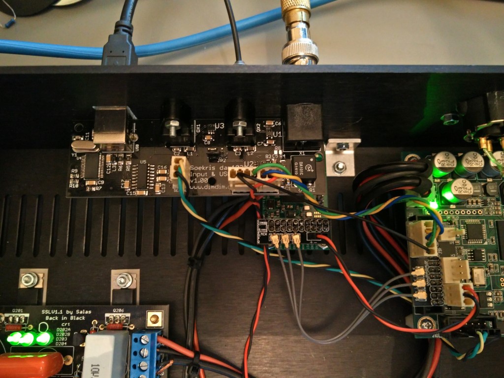
I built one for my Soekris, but it is a bit more than just a small board for the coax input:
This circuit haven´t extra current.5v ldo regulator, is it capable for the extra bc550-560 current?
The +5 and -5 vol. ldo power current in to LTSpice simulations with transistors is similar (even slightly lower) than the original.
If this is about 3083 post:
http://www.diyaudio.com/forums/vend...-magnitude-24-bit-384-khz-62.html#post4390174
Before everybody start adding transistors, please note that there is a reason I use the opa365, it have a Vos spec of max 0.2mV. Adding transistors out of the loop, the Vref will not track anymore, resulting in larger 2nd harmonic distortion.
The Alecm circuit haven´t feedback in the transistor output. This output 3,6 V. is diferent to Vref 4 V. an +V is diferent amplitude than -V (larger 2nd harmonic distorsión).
In this mod output is identical to Vref an +V amplitude is identical to -V. Will track Vref better than the original and other previous mod because transistor is in the loop. Have not larger 2nd harmonic, have equal or less than the original because the voltage remains equal the Vref better than the original or previous mod.
One more thing, you can't have that small load resistors, you exceed the current (and power) capacity of the +-5V regulators. Unless you use some other +-5V regulators.
Alecm circuit add 24 Ohm output resistor (48 Ohm +V to -V). This add 150 mA to maintain the 3.6 vol. output this is 300 mA more to the +5V ldo regulator and -5v ldo regulator. This can damage the regulator.
In this transistor mod no resistance is added so current provided by ldo +5 and -5 vol is the same than original. They work with the same current and can not be damaged.
That is true.And I repeat, doing large and/or complicated modifications can easily damage your dam1021.
 It is complicated and can easily damage your DAM board like the other mods.
This looks nice, so you have isolated SPDIF and USB on the same board right?
Exactly, plus 2 toslink inputs and local LDO regulators to power it all independently from the DAM.
The Alecm circuit haven´t feedback in the transistor output. This output 3,6 V. is diferent to Vref 4 V. an +V is diferent amplitude than -V (larger 2nd harmonic distorsión).
on the first hand it is good to see that transistor approach is having development and interesting here. For some reasons Soren has negative onto my mods, so i have stopped to write here.
3.6V it is one of very old former approach. Now , after many hours of listening with top DACs and research, I have a completely different scheme based on transistors with 4V.
My version, of "Oneclock's" vref mod + 16x470uf!
Before, my mod was "hifiduino mod" 16*470uf caps plus removed output opamps!
Better bass better highs and better depth at first listen...!
PS: alecm share with us your approach!
Thanks to all members!
Before, my mod was "hifiduino mod" 16*470uf caps plus removed output opamps!
Better bass better highs and better depth at first listen...!
PS: alecm share with us your approach!
Thanks to all members!
Attachments
There are now 100uF X5R caps in 0805 size available:
http://www.farnell.com/datasheets/1957830.pdf
May be an interesting alternative for the Vref buffer.
http://www.farnell.com/datasheets/1957830.pdf
May be an interesting alternative for the Vref buffer.
I have done BC's added to v2 soekris and it is big difrence with bas, stereo and lokalizations. Must have ! Im not elektronic but mayby it is pasible to do somthing with clock stabilizer? for now i have added capacitors, but mayby it is pasible to ad something like BC transistor?
I noticed paul disabled his post regarding vref modding "the final frontier". I'm hoping he's just working on an updated post rather than getting annoyed at any new comments regarding the transistor mod. This was after I posted a comment regarding the transistors being in the op-amp feedback loop thus keeping the tracking.
I noticed paul disabled his post regarding vref modding "the final frontier". I'm hoping he's just working on an updated post rather than getting annoyed at any new comments regarding the transistor mod. This was after I posted a comment regarding the transistors being in the op-amp feedback loop thus keeping the tracking.
I just don't have time to update the vref posts at the moment, so I've taken them down.
There are some issues with the sims of the vref, to the point I think it's safe to say any sim that hasn't been verified by real world testing should be treated with a healthy amount of scepticism.
What I've found is that the .noise sims tally up in terms of broad trends with the white noise testing of the vref. This is because the white noise is basically a steady state load, and the vref buffer is not subject to the same kind of load variation as with sine or square wave tests.
Once you start looking at more dynamic test signals the sims become significantly less accurate. It has been pointed out by zfe and others that the load presented to the vref by the shift registers and R2R ladder is very complex, so it's not so surprising that it's difficult to simulate dynamic loading accurately.
I'm finding with the low-res mod and 2700uF per vref that there is a loss of dynamics, which is one of the reasons I was looking at possibility of using staggered cap values, rather than 4 or 5 x single value. I want to take a look at the bc560/550 mod at some point to see if this helps, but I want to do before//after measurements to see what effect this mod actual has.
The other niggle is the "super reg" supply I'm using is still dumping crap into the ground of the DAM at low level despite having replaced virtually everything except the transformer. The noise is high enough that it just breaks through above the level of ripple on the vref when playing back white noise. For the square and sine tests, the noise is actually a dominant factor in the vref posts so makes it hard to see what is going on. I'm still clinging to the faint glimmer of hope it's my build not the design, but I'm running out of part replacement options.
alecm,
Just because SOEKRIS does not agree with your approach does not mean you have been told to not post here.
As the manufacturer he has to be careful that what he says is not misunderstood. So far, SOEKRIS has not recommended any mods other than the ones he has offered. He does not need someone complaining that their no longer working board is somehow his fault.
As he has made clear, he is more than happy to sell us another board so solder away just don't expect him to give his approval of anything.
So please show us what you are doing.
I have found he will answer questions concerning our modification ideas but they best be specific and not asking for "how to do" something beyond what is in the manual and what he has recommended. After that, we are on our own.
AS time has gone by and more of the "mysteries" of the circuit have been found he has not shown any disgruntlement. I think he has enjoyed observing the process. Nonetheless, I wish he would go ahead and release a schematic!
Sorry for the repeat, but I saw nothing that would indicate your work and observations are not wanted. You just cannot expect him to embrace them and none of us are immune to criticism. He simply did not think your approach was a good one. He, too, is entitled to his opinion.
I know I have missed your posts.
Hoping we can look forward to hearing from you often.
- Home
- Vendor's Bazaar
- Reference DAC Module - Discrete R-2R Sign Magnitude 24 bit 384 KHz