An current feedback amp produce a large step on the input because of its nature. (Low Z feedback network produces high peak currents in buffer frontend in an CFB amp)
An diamond buffer has two stages, this TSSA V1.7 has two stages made with the CFP pairs. The SSA variant only has one stage buffer -> fluctuation currents on the input is beta factor times higher on the SSA than on the diamond buffer or the TSSA CFP input pair. With BC850C/860C that would give you currents that are ~600x higher on the input that the preamp has to drive!
So there you need a low Zout preamp with very wide bandwidth.
Well I must admit that you lost me there....
Unfortunately I am a man of practice and not the theory ....in the past this has resulted in very expensive errors...(maybe thats the reason for the sudden crisis mmmhh). So these days I go with the advice of the experts...
Short: Use an passive preamp but the DCB1 is better for the job, and has no feedback.
But are there through hole external resistors for fixing the gain and instructions in V1.7 as in the previous amp?
There is one trimmer less and trim range is much better.
Short: Use an passive preamp but the DCB1 is better for the job, and has no feedback.
It is indeed wide bandwidth single stage that has 100% self feedback being a JFET source follower buffer, but I would think you refer to the absence of an external and reactive multistage feedback loop.
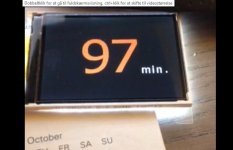
We have made an user interface for an customer with an TFT display. More or less all the software and hardware can be reused for a user interface for an preamp.
I have set Kristian my colleague on the Job changing it to something usefull for an preamp.
The display is 240 x 160 x 24bit.
Let me know if this has any interrest?
I have set Kristian my colleague on the Job changing it to something usefull for an preamp.
The display is 240 x 160 x 24bit.
Let me know if this has any interrest?
Attachments
Hi all.
Sorry for the long delay.
I have got this message today.
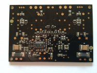
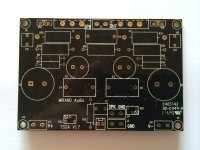
"TSSA V1.7 boards finished, however, we made the mistake with soldermask color, we made them as green soldermask, however, you ordered them as black, if green soldermask acceptable? Or we will arrange remaking and it takes about 6-8 days for remaking."
So we need to add 6 - 8 days. As i want them to be black. They look the best this way.
Sorry for the inconvenience it causes!
Sorry for the long delay.
I have got this message today.
"TSSA V1.7 boards finished, however, we made the mistake with soldermask color, we made them as green soldermask, however, you ordered them as black, if green soldermask acceptable? Or we will arrange remaking and it takes about 6-8 days for remaking."
So we need to add 6 - 8 days. As i want them to be black. They look the best this way.
Sorry for the inconvenience it causes!
Thank you for the kind offer - very tempting indeed. Send me a PM with the details and costs. Thanks again. All the best, PerPer, what we Can do is to build it for you. We have a case already that we could use. Simelar to the one on the pictures.
No problem for me as the rest of my setup is not ready anyway :-( All the best, Per... So we need to add 6 - 8 days ... Sorry for the inconvenience it causes!
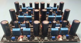
A good job done, always takes time. Nice attention to detail Sonny.
P.S. What spec SMD resistors you used?
I use standard SMD resistors with 1% tolerance. Even though it performs better than the previous version with metal foil SMD resistors.
Adjustment procedure can be done under 5 minutes per channel using the 8 steps below.
Armed with an DMM with alligator probes it is fast and straight forward to adjust the amps.
Before adjustment we need to calculate the desired bias current. Formula is U-R30 = Ibias * 0.05 => Ibias = 0.4A => U-R30 = 0.4 * 0.05 = 20mV.
1) Check that the power is connected correctly. V+ to V+, GND to GND, V- to V-, SPEAKER to SPK OUT and SPK GND.
2) Measure across R30.
3) adjust R30 to 10mV using R22 (CW is more bias voltage)
4) Measure across speaker terminals
5) adjust DC offset using R21 on speaker terminals to 0V (Or +/-10mV is okay, but it is pretty much static as it does not fluctuate at all..") )
)
6) Finally measure across R30 again (The voltage changes with the bias adjustment. But bias adjustment does not move the DC offset more than a few millivolt)
7) Adjust R30 to 20mV (0.4A bias) using R22.
8) recheck DC offset on speaker terminals. If it is within +/10mV then it is fine!
Done!!
As said the bias the very static so there should be no need to recheck it.
Armed with an DMM with alligator probes it is fast and straight forward to adjust the amps.
Before adjustment we need to calculate the desired bias current. Formula is U-R30 = Ibias * 0.05 => Ibias = 0.4A => U-R30 = 0.4 * 0.05 = 20mV.
1) Check that the power is connected correctly. V+ to V+, GND to GND, V- to V-, SPEAKER to SPK OUT and SPK GND.
2) Measure across R30.
3) adjust R30 to 10mV using R22 (CW is more bias voltage)
4) Measure across speaker terminals
5) adjust DC offset using R21 on speaker terminals to 0V (Or +/-10mV is okay, but it is pretty much static as it does not fluctuate at all..
)6) Finally measure across R30 again (The voltage changes with the bias adjustment. But bias adjustment does not move the DC offset more than a few millivolt)
7) Adjust R30 to 20mV (0.4A bias) using R22.
8) recheck DC offset on speaker terminals. If it is within +/10mV then it is fine!
Done!!
As said the bias the very static so there should be no need to recheck it.
The buyers list
vgeorge 2 without mosfets ECW20N/P20-Z + Salas 2
buzzforb 2
pdb 2 + 2 capkits
Michael G and on of his fellows 6. (He already has 2 running)
An externally hosted image should be here but it was not working when we last tested it.
Next batch ready to ship.
- Status
- This old topic is closed. If you want to reopen this topic, contact a moderator using the "Report Post" button.
- Home
- Vendor's Bazaar
- TSSA V1.7 mosfet Current feedback amp module