Perfect would look forward to the pricing. Would you have a stereo chassis as well to accommodate two psus?
For first one
Sent from my ONE A2003 using Tapatalk
Hopefully I got what you mean, well yes stereo and monoblock chassis are going to be ready to be delivered maybe even from next week on, will do my best. Stereo chassis - Black Mamba normally accomodate two SMPS1200A400, dual mono, and monoblock chassis - MonoLith accepts one First One module together with one SMPS1200A400.
")
What's new is that the First One Large will be full balanced monoblock (two counter phase modules) with one SMPS3K400, now that will be the beast, same sound signature with no power limit.
.....What's new is that the First One Large will be full balanced monoblock (two counter phase modules) with one SMPS3K400, now that will be the beast, same sound signature with no power limit.
You tested bridged version and it got the stamp approved
.... also like you intend match output devices for L-version with new bench tool think that is serious good policy.Hi BYRTT
Thanks for the tip. I'll test this simplest ever bridging adapter with two First One modules, maybe next weekend.
Theoretically it is correct and it should work. I agree that this would be the most clear and transparent bridging adapter ever, without need of any messy electronic circuit in front of First One.
L.C.


Tomorrow I'll go to production facility and check if some v1.2 are hiding somewhere around the storage, under the tables, behind the furniture ...
What happened?
it was blown a few months ago but i didn,t have the time to deal with it.
now i read somewhere your sales for the 1.2 (a little late)and i thought to ask
if something is left.
Isn't it called 'bridged' (as here)? Balanced is about matched impedance / differential amplifier (that could well be single-ended as here) and separating groud currents from signal path. I actually would be more happy to see balanced inputs rather than bridged outputs...What's new is that the First One Large will be full balanced monoblock (two counter phase modules)
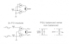
If you happy to see balanced inputs and at same can live with amp also get bridged outputs it should be possible, below first schematic is copy your link to bridge amp, then couple as in lowest schematic and you have fully balanced input. Can't predict if it would run trouble free on balanced PSU, but pretty sure on non balanced PSU with virtual ground it would work.
There is more info in these previous posts http://www.diyaudio.com/forums/vend...-mosfet-amplifier-module-260.html#post4631021 and http://www.diyaudio.com/forums/vend...-mosfet-amplifier-module-262.html#post4632837.
Attachments
No, not bridged. Fully balanced input/output, matched impedance differential amplifier, couldn't be more differential than this, you'll see.
The input (cabling) is properly balanced, but the amplifier itself in your topology is still two separate unbalanced amplifiers, not the difference amp. If the input signal has not symmetric voltage - you get only 1/4 of possible max power on the output...If you happy to see balanced inputs and at same can live with amp also get bridged outputs it should be possible, below first schematic is copy your link to bridge amp, then couple as in lowest schematic and you have fully balanced input.

The topology drawing would be the best explaining.No, not bridged. Fully balanced input/output, matched impedance differential amplifier, couldn't be more differential than this, you'll see.
But what I meant is to have also properly balanced single-ended output smaller versions (M and S). So we could have ground loop resistant smaller amps that could be combined with single PSU etc. without worry about possible hum and have the best S/N ratio non-interfering with best common mode rejection.
Last edited:
Agree about serious approach to the strongest of the First Ones, only PCB design took me few months, no shortcuts were taken..You tested bridged version and it got the stamp approved
For example, there are no source resistors, not needed actually but still you get almost ideal Id tracking from paralleled devices from zero to Id max, that have positively surprised me, how good these lateral mosfets really are. First four L modules will be tested in depth before ordering a series..
.... there are no source resistors, not needed actually but still you get almost ideal Id tracking from paralleled devices from zero to Id max, that have positively surprised me, how good these lateral mosfets really are...
Great news Andrej. Congrats !!!
The 1.2 is green
Sent from my ONE A2003 using Tapatalk
seems like there are both green and red 1.2s
LC i have a couple of pm's from members with a single 1.2 version left.
Does it matter if it is green or red pcb?
mine are green.
The 1.2 is green
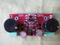
At start FO v1.2 were green in second batch we made them red since that was a PCB design of our future amps like FO M and LTo end the confusion....
The picture is not very good but you see a Red V1.2 Module...
R.
Fully balanced First One
No worries, all First One modules will stay unbalanced input as till now. With fully balanced topology, the concept is to preserve original differential signal from the source not to make new subtraction in FO amp's front-end, it is meaningless even wrong to do that. Once the signal is differential, high Z from GND, there's no reason to differentiate it again and again every time in every unit in the signal path, for me that is wrong since it introduces new distortions and subtraction deviates unnecessarily.
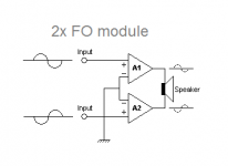
My point is to make balanced amplifier which amplify both phases of the signal independently and summ them at the speaker itself. Pic below explains it well (thanks BYRTT).
BTW how's your FO v1.4 M advancing towards finish?
L.C.
Hi DoHi LC,
Are you planning new revs of S and M using fully balanced differential topology like the L version?
Thanks
Do
No worries, all First One modules will stay unbalanced input as till now. With fully balanced topology, the concept is to preserve original differential signal from the source not to make new subtraction in FO amp's front-end, it is meaningless even wrong to do that. Once the signal is differential, high Z from GND, there's no reason to differentiate it again and again every time in every unit in the signal path, for me that is wrong since it introduces new distortions and subtraction deviates unnecessarily.
My point is to make balanced amplifier which amplify both phases of the signal independently and summ them at the speaker itself. Pic below explains it well (thanks BYRTT).
BTW how's your FO v1.4 M advancing towards finish?
L.C.
Attachments
- Home
- Vendor's Bazaar
- First One - mosFET amplifier module