Thanks Christophe, happy and prosperous year at your new home location and all the best in 2015. ")
Well as most CFA designs here on DIY, First One v1.4 will also be throughout DC coupled, still not quite the same as in Slewmaster series, more like my TSSA design elements, partly. Accuphase also has nice and simple basic CFA core, will see. The aim is to make sch as simple as possible but still HF and thermally stable, with low THD performance. A lot of ideas to choose from but at the end the most important will be optimization by listening tests started early next week. It has to be firm step forward from v1.3 with at least the same change ratio as from v1.2 to v1.3, which would be quite remarkable achievement if succeeded.
I will sophisticate sch gradually, with each step to be evaluated separately, trying to avoid missed steps. Still a lot of work ahead, without blood, sweat and tears no success is possible.
Regards to all, L.C
Last edited:
Thanks Theo, all the best in 2015
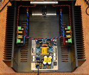
At the moment First One v1.4 on the test bench, being measured and assembled in a chassis. Main advantage of this version is complete DC coupling, even better SQ and drop in replacement for previous versions. Higher power level can be achieved in bridge mode or by paralleling the FO modules or by combining the two principles.
Maybe there will be four outputs/higher rails version in the future but nothing like that on horizon at the moment.
I can pretty convincely say that all possible parts combinations and permutations in First One design have been explored and evaluated by listening tests, allways compared to the best posible version incarnation at present time. I know this amp very deeply, also knowing its weak points, new ideas have led me to explore further more in wider, broader schematics arena, which was intentionally avoided at begining of this thread. I tested DC coupled diamond CFA long before even started VSSA and telling you honestly I didn't liked it at all, now learning few tricks on the long journey passed, makes me much more confident that new v1.4 will be firm step ahead.Hi there ! you said too much or not enough !!
one key things of vssa&FO was the virtual ground with the 2 big caps in each current source branch, now you seem moving to a more traditional cfa approach isnt it, did you get convinced by Esperado ??! cant wait
cheers
But as always on the market people wants more, better quality, First One v1.4 will be the answer to these wishes, having all that.
Very nice and clean layout as it should be, congratulations. Input wire should be OFC solid core twisted pair for the best SQ.Thank You Lazy Cat! A very nice amplifier you have created!
You're probably the first one implemented Coldamp SMPS, how do you like it since it has regulated output voltage?
Regards L.C.
Multi Channel Success
Hi Guys,
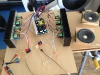
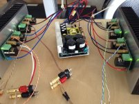
I wanted to post some pictures of my multi channel test setup as it works!
I have four channels running from one SMPS1200A180. Output voltage from power supply is measured as +/- 47 V.
The SMPS started up fine took a couple of seconds before the relay clicked and then power to all four modules was supplied.
Unfortunately my test setup let me down and I have a slight problem. I was using an ipod for input and the cable had a bad connection and this has caused some of the resistors to smoke.
The problem is repeatable as when I was testing the other side it happened again!
It does not stop the amp from functioning and I cannot detect any difference in the sound although as you can see the test speakers are not too revealing.
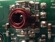
I have attached a picture showing the scorching on the resistors. The picture is not great but you can see the difference between the upper resistor where the text is whiter. I turned the power off quickly so the scorching was minimal.
The resistors affected are R26, 27, R30 and R31 the ones closest to the inductor marked as 39R0.
LC, can you tell me what part of the circuit these parts are in and if I need to replace them?
Hi Guys,
I wanted to post some pictures of my multi channel test setup as it works!
I have four channels running from one SMPS1200A180. Output voltage from power supply is measured as +/- 47 V.
The SMPS started up fine took a couple of seconds before the relay clicked and then power to all four modules was supplied.
Unfortunately my test setup let me down and I have a slight problem. I was using an ipod for input and the cable had a bad connection and this has caused some of the resistors to smoke.
The problem is repeatable as when I was testing the other side it happened again!
It does not stop the amp from functioning and I cannot detect any difference in the sound although as you can see the test speakers are not too revealing.
I have attached a picture showing the scorching on the resistors. The picture is not great but you can see the difference between the upper resistor where the text is whiter. I turned the power off quickly so the scorching was minimal.
The resistors affected are R26, 27, R30 and R31 the ones closest to the inductor marked as 39R0.
LC, can you tell me what part of the circuit these parts are in and if I need to replace them?
Attachments
LC, can you tell me what part of the circuit these parts are in and if I need to replace them?
These are part of the output zobel and you can easily check if the values have changed as there is a cap in series with each. I would replace them on principle.
Analog Sa
Thanks for the info. I have measured a good module and they are all 39 Ohms.
The scorched ones measure as 39, 41 and 49.
I am not sure how easy it will be to replace these as I don't have an SMD rework station.
Are the parts glued down or will they come away easily enough with a soldering iron and tweezers?
I have installed insulating washers.....
Is heatsink at ground potential or a nearby floating antenna warming up zobel network.
The scorched ones measure as 39, 41 and 49.
I am not sure how easy it will be to replace these as I don't have an SMD rework station.
Dunno what to say... one is clearly off, but it's probably preferable to leave things as they are if you have no equipment or experience with smds.
Two normal soldering stations will suffice, but you should experiment on some less audiophile boards first. And what better excuse to buy a hot air station?
Nice four channels layout.LC, can you tell me what part of the circuit these parts are in and if I need to replace them?

What you have to know is the heatsinks are normally part of a grounded chassis, but in your case both of them nicely floating in mid air as an electric potential concerns. It would be fine to connect heatsinks to common earth potential, also in between testing period, otherwise each heatsink will act as a nice antenna, picking up el. mag. signals and forcing them directly to module's GND potential, which is not so good. Large HF signals at amp's output cause zobel resistors to dissipate few Watts, which is quite normal but only for a short period of time. Output power mosfets can withstand these signals at much higher extent without any problem, since zobel resistors wattage is calculated to amp's full swing at 40 kHz, higher frequencies than that will make these resistors to smoke or even die in flames. Originally these are 39 Ohms, four in parallel can dissipate 3 W. In your case if they still measure 36-42 Ohms leave them as they are otherwise replacement is recommended.
Hello to all
I'm in the process of building my first one amp, but i have some questions:
I have 2 Hypex SMPS1200 one for each FO module, Could you please guide me on how to connect the power on switch??
How to connect the Led??
Thanks for your help.
Yes, later today.
- Home
- Vendor's Bazaar
- First One - mosFET amplifier module