No photo, card and power still on a board and not in a box before the next cards.
It is much more comfortable for modifications.
JLester
For the deletions of the ca3.6 and cb3.6 white Led version, am I correct?
View attachment ca3ca6cb3cb6.pdf
Roger
It is much more comfortable for modifications.
JLester
For the deletions of the ca3.6 and cb3.6 white Led version, am I correct?
View attachment ca3ca6cb3cb6.pdf
Roger
D
Deleted member 148505
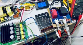
Bobo, do you have a picture?
No photo, card and power still on a board and not in a box before the next cards.
It is much more comfortable for modifications.
JLester
For the deletions of the ca3.6 and cb3.6 white Led version, am I correct?
View attachment 912983
Roger
Deletion of ca3.6 and cb3.6 is for Versions V1, V1A, V1B.
I'm using V1B and got shocking result (but you guys are not lol), so I think you also need to replace RA7 and RA8 to 2.2 ohms since it is default on V1A and V1B.
Regards,
Lester
D
Deleted member 148505
Is it the capacitors with a red dot on my pdf?
Thanks
Yes, correct
Deletion of ca3.6 and cb3.6 is for Versions V1, V1A, V1B.
I'm using V1B and got shocking result (but you guys are not lol), so I think you also need to replace RA7 and RA8 to 2.2 ohms since it is default on V1A and V1B.
Regards,
Lester
what is the purpose of reducing this resistance value? can i just short it out?
D
Deleted member 148505
what is the purpose of reducing this resistance value? can i just short it out?
Using RA7/RA8 helps with stability (although the amp is still stable if we short them). Since we are using PFFB and have removed C_Op feedback caps, shorting out RA7, RA8 might make the amp unstable in some conditions (we have different setups so it's risky to recommend shorting them).
We are reducing the value to get optimum sound without compromising stability.
Add (or delete) resistors in series with opamp's power supply rails
My hunch is correct that the sound is being limited by the opamp feedback caps. Might be the group delay between the opamps are different.
In slaa788A, they increased it for stability from 22pF to 330pF (corner freq is ~48kHz in PFFB).
I think as long as the module is stable, the value can be decreased. In my module, the whole amp is stable even when the opamp feedback caps were removed (using LME49860).
-----------------------
Further upgrade is matching the resistors of SE to Diff buffer, as well as PFFB resistors. It will lower down the distortion further.
Hello
Aop input / output with 330pF 10kHz
Best regards
Roger
Attachments
D
Deleted member 148505
Hello
Aop input / output with 330pF 10kHz
Best regards
Roger
Output of opamp or the amp module?
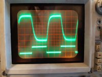
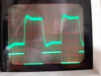
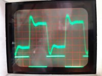
At the 4 Ohm and 8 Ohm output whatever the 0 or 330pF capa, photo at 10kHz ( the 450kHz residue is about 1.08V c / c 0.76 rms)
Best regards
Roger
Best regards
Roger
Attachments
Last edited:
D
Deleted member 148505
At the 4 Ohm and 8 Ohm output whatever the 0 or 330pF capa, photo at 10kHz ( the 450kHz residue is about 1.08V c / c 0.76 rms)
Best regards
Roger
330pF feedback caps were removed in those measurements? If yes, then our amp is stable
") slaa788A page 48 has same overshoot levels (1kHz).
slaa788A page 48 has same overshoot levels (1kHz).I will post similar measurements by February.
Regards,
Lester
Lester,
What are your thoughts on pma's measurements in this post and onward in that thread?
On Class D Amplifiers Measurements | Page 28 | Audio Science Review (ASR) Forum
On Class D Amplifiers Measurements | Page 29 | Audio Science Review (ASR) Forum
AIYIMA A07 TPA3255 Amplifier Measurements and Review - LM4562 option | Page 3 | Audio Science Review (ASR) Forum
AIYIMA A07 TPA3255 Amplifier Measurements and Review - LM4562 option | Page 3 | Audio Science Review (ASR) Forum
Last edited:
D
Deleted member 148505
Yup I've seen those measurements. I think that should be the typical performance (at low-ish rail voltage) of a TPA3255 amp without using fancy regulators and optimization. Using OPA1656 may improve 2nd or 3rd harmonic by -3dB.
I may send TPA3251 instead of TPA3255 for measurements if I get better THD performance out of it (at same rail voltage).
I may send TPA3251 instead of TPA3255 for measurements if I get better THD performance out of it (at same rail voltage).
D
Deleted member 148505
It's really interesting that some people find a more pleasing sound with PFFB, given the measurements we're seeing.
PFFB tames the harshness at the upper end and makes the sound softer.
D
Deleted member 148505
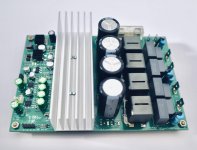
Just got my V1 board in my system. Did the C17 mod and also removed those tiny opamp bypass caps.
Running as supplied with Silmics all round and the LME49860.
Slightly different setup than before using my 3e board in that I have built a LT4320 based rectifier. I now get just under 51v...up from 48v with the previous monolithic bridge rectifier. The JLE amp is cooler at 51v than the 3e was at 48v. The inductors noticeably so.
Listening commences now but for the short half hour it's been on I have no concerns at all! Sounds very good
D
Deleted member 148505
Just got my V1 board in my system. Did the C17 mod and also removed those tiny opamp bypass caps.
Running as supplied with Silmics all round and the LME49860.
Slightly different setup than before using my 3e board in that I have built a LT4320 based rectifier. I now get just under 51v...up from 48v with the previous monolithic bridge rectifier. The JLE amp is cooler at 51v than the 3e was at 48v. The inductors noticeably so.
Listening commences now but for the short half hour it's been on I have no concerns at all! Sounds very good
Nice
Also place fuse to the secondary side of your power supply, the SCR circuit will self-destruct at 62V DC input. (if your area has unstable mains). The TVS diode will start to conduct at 53V DC so it will catch some DC transients. (So don't worry )
D
Deleted member 148505
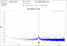
This is the performance of my very first TPA3255, (1st iteration module Jan 26, 2020) . I'm only using LM317 as 12V regulator and NE5532 SOIC-8 buffer opamps.
FFT is not properly labeled (IRCore350M lol) Signal is attenuated to 500mVrms (greater than that and the QA400 input will saturate)
At 4 ohms 10W output, notice that the second and third harmonics are just around -110dBV. Though the fifth harmonic is high..
Because of LM317, Noise floor is not optimal so THD+N performance is just average.
I believe that this is the 'typical' performance of TPA3255.
Those inductors are really good btw, although they get hot at high voltages.
Attachments
- Status
- Not open for further replies.
- Home
- Vendor's Bazaar
- Amplifier Modules and PCBs For Sale