D
Deleted member 148505
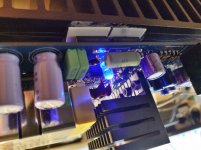
It's alive
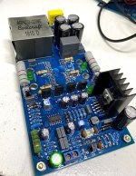
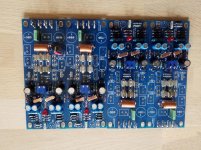
Finished one channel of your amp and it runs perfect, no audible hiss on my JBL tweeters,
So I'm off to drill heatsink and get some real power, and some measurements.
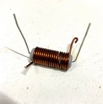
I will find more suitable power resistors to, project was cheap, I had some irs2092 chips, and I made a sample request at coilcraft, and they send me these nice inductors for free, so if you're building jle amp, it might be an idea for a free sample request for inductor
Finished one channel of your amp and it runs perfect, no audible hiss on my JBL tweeters,
So I'm off to drill heatsink and get some real power, and some measurements.
I will find more suitable power resistors to, project was cheap, I had some irs2092 chips, and I made a sample request at coilcraft, and they send me these nice inductors for free, so if you're building jle amp, it might be an idea for a free sample request for inductor
Attachments
D
Deleted member 148505
D
Deleted member 148505
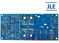
IRCore2000 V1.1 Blank PCB now available
Now available on my eBay Merch
2pcs Blank PCB: IRCore2000 V1.1 Class-D Amplifier PCB | eBay
Now available on my eBay Merch
2pcs Blank PCB: IRCore2000 V1.1 Class-D Amplifier PCB | eBay
Attachments
Great success
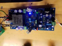
Got the pcb with premounted smd, thanks lester, one board running, but struggled alot with heatsink on totempole drivers, had to saw and grind, is there any heatsink that's plug and play?, you think surface is sufficient for high power continuous? Heatsink is 40mm by 40, with a few fins removed
Got the pcb with premounted smd, thanks lester, one board running, but struggled alot with heatsink on totempole drivers, had to saw and grind, is there any heatsink that's plug and play?, you think surface is sufficient for high power continuous? Heatsink is 40mm by 40, with a few fins removed
Attachments

Hi again.
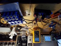
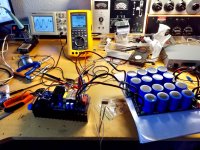
A have today tried and power test the 2000-d module, it is hooked up to a 1.2kw 45v, 65 volt dc, 160000uf, dummy load is 8 ohm, 1khz.
My question is as you see in pic if I raise volume beyond 36v arms output, the wave flattens out like its hitting rail voltage, why is that happening ?? Output in 8 ohm is 150w
Attachments
D
Deleted member 148505
Got the pcb with premounted smd, thanks lester, one board running, but struggled alot with heatsink on totempole drivers, had to saw and grind, is there any heatsink that's plug and play?, you think surface is sufficient for high power continuous? Heatsink is 40mm by 40, with a few fins removed
A 40mm x 20mm copper or aluminum plate is sufficient, no need for finned heatsink. I will update BOM with suitable part number but we still have to drill holes.
Tried putting scope in average mode and found out it was the 300khz carrier wave interfering, was able to get 41v clean since, above that it started some clipping.
What is the rail voltage at clipping point?
Yes carrier residual is still present because there are no onboard filters to remove it. You can put additional filters on a breadboard, I'll update the build guide. Thanks!
Attachments
D
Deleted member 148505
Happy new year!
I haven't tried stereo listening comparison yet. But some of my clients prefer my modules with IRFB4227 on them.
Whoua Jlester a new IRS Hi-end module, great !
Ahh i can resist to test him... sound versus JLE-800S ?
PS: picture in first page is no longer visible...
I haven't tried stereo listening comparison yet. But some of my clients prefer my modules with IRFB4227 on them.
D
Deleted member 148505
Hi Lester, do you currently have any class d boards that will support +-90v rails (unregulated toroidal) as i have a few of these transformers. Greg
For now we don't offer class-d boards with > +/-75V rails. But I will design board for IRS2452AM once it becomes available on more electronic distributors.
Hi Lester,
How do you mount the Mosfets with your version of the GB150D? Using wires, or flat under the board? I note the original had the Mosfets near the edge of the board.
How does it perform on the scope? I remember Bigun from this forum had issues with stability when he made his version of this amp.
Thanks
Stuey
A quick question jlester.
It's regarding the greg ball amplifier.
I have four 300 watt toroidal transformers , and label says 36 volt on secondary, that adds up to the 50 volt dc the amp needs, all fine, except the transformers are old and back then our grid was 220 volt, so I measured them at current 230v grid unloaded, and they deliver +/÷56 volt dc, can the ska150 handle the extra voltage?
Thomas
D
Deleted member 148505
Hi Lester,
How do you mount the Mosfets with your version of the GB150D? Using wires, or flat under the board? I note the original had the Mosfets near the edge of the board.
How does it perform on the scope? I remember Bigun from this forum had issues with stability when he made his version of this amp.
Thanks
Stuey
Hi.
I answered the same question and got this response, they are mounted flat under the board, sticking out the sides, the bd139/140 go on top of the mosfet.
As to stability I don't know, I'm waiting for boards, but am pretty sure they are stable
Yes that's how it is mounted, very well explained
")
Regarding scope / thd measurements, yes it's stable, I'll publish them soon. I got busy with TPA3255 lately.
A quick question jlester.
It's regarding the greg ball amplifier.
I have four 300 watt toroidal transformers , and label says 36 volt on secondary, that adds up to the 50 volt dc the amp needs, all fine, except the transformers are old and back then our grid was 220 volt, so I measured them at current 230v grid unloaded, and they deliver +/-56 volt dc, can the ska150 handle the extra voltage?
Thomas
SKA GB150D can handle it but you can only use it for 8 ohms speakers.
Output stage of this amp is not designed for more than 150W at 4 ohms.
For home use / casual listening, 4 ohms is fine. But for party level volume / RMS output measurements, it's not advisable.
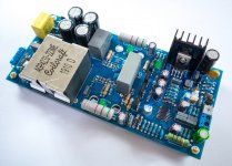
Photos often say more, i glued copperbar on top of the matched bc546c bc556c to thermally stabilize them, in case you were wondering.Hi Lester,
How do you mount the Mosfets with your version of the GB150D? Using wires, or flat under the board? I note the original had the Mosfets near the edge of the board.
How does it perform on the scope? I remember Bigun from this forum had issues with stability when he made his version of this amp.
Thanks
Stuey
Attachments
Last edited:
D
Deleted member 148505
Nice idea about the copper bar.
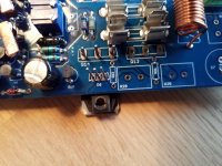
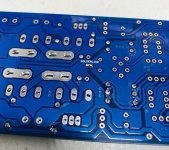
Also don't forget to put solder blob on solder link under the PCB. (attached picture) And put parallel 10 ohms with the output inductor.
Looks like your mosfet has a different package? or is it just a dummy?
I separated the power ground plane from input ground plane so that I can experiment with it.
Attachments
- Status
- Not open for further replies.
- Home
- Vendor's Bazaar
- Amplifier Modules and PCBs For Sale