D
Deleted member 148505
Is the 682KL very far along on the path of diminishing returns? Quantitatively, what's the impact of using 682KL vs 103KL on higher harmonics (HD4+) and IMD? And would there be anything to gain by using air core inductors?
Jantzen Audio 0.010mH 20 AWG Air Core Inductor Crossover Coil
Yes, use the 6.8uH if you want to lessen the THD by another -3dB to -6dB. (We want to win ASR performance race for TPA3255)
Of course there will be some trade-offs if we will use 6.8uH. Soundwise you can get more noticeable gains by changing the input cap and/or opamp, or bypassing the buffer section (best).
I was testing my modified TICore260BTL module awhile ago and noticed that the THD+N is clipping early, so I checked TPA3251 PFFB graphs and it does agree with what I measured. So I will revert the changes except for the inductor. Now I want to use 48V rails again for my ASR build (facepalm)
Some quotes from slaa701a
"Generally, the higher the inductance (the more turns of wire) for a given core material, size, and geometry, the less linear the inductor."
"Increasing the inductance reduces the output ripple current, and better efficiency is generally observed."
"For the TPA32xx family of devices, a 7-µH inductor is a better value for performance-oriented applications due to improved linearity and generally improved distortion performance over higher inductances. However, for a more power-efficient system, 10-µH may be a better selection due to the reduced ripple current with a slight penalty on performance. In both cases, core loss must be considered as well as DCR. Although a 10-µH inductor may show improved power dissipation for low output power due to reduced ripple current, if it has high DCR, the losses may be greater at high currents than a 7-µH inductor with higher ripple current."
------------
As for the Jentzen aircore, it has a high DCR of 70 mOhms, not suitable for TPA325X since it will heat up. Can you find its L vs Current performance?
I assume for an air core it’s pretty much constant, but I’ll have a look. Note that it’s a 20 AWG winding so with 16 or even 14 the DCR would be substantially reduced.
http://www.meher-mangoldt.com/downl...and ICR for MV Power Quality Applications.pdf
I suppose the linearity would be affected by resistive heating (copper has a non-zero TCR) but I don’t think it would impact inductance value?
http://www.meher-mangoldt.com/downl...and ICR for MV Power Quality Applications.pdf
I suppose the linearity would be affected by resistive heating (copper has a non-zero TCR) but I don’t think it would impact inductance value?
Last edited:
D
Deleted member 148505
I assume for an air core it’s pretty much constant, but I’ll have a look. Note that it’s a 20 AWG winding so with 16 or even 14 the DCR would be substantially reduced.
http://www.meher-mangoldt.com/downl...and ICR for MV Power Quality Applications.pdf
I suppose the linearity would be affected by resistive heating (copper has a non-zero TCR) but I don’t think it would impact inductance value?
Yes ideally the aircore is linear, advantage is that it does not saturate at all.
That's why we are using the overkill VER2923 inductors so that TPA3255 will operate in the inductor's linear zone.
VER2923 is still linear at 35A, way above the overcurrent protection limit of TPA3255 at 17A.
")
DCR = 2.6mOhms max, low dissipation factor and we have a winner.
Also aircore inductors have a large stray field outside its mechanical dimension, so the position of multiple aircore inductors is vital to the amp's performance. Stray field might affect other parts of the module.
Managing the large stray field and keeping the heat low will be the challenges for using aircore inductors.
Last edited by a moderator:
D
Deleted member 148505
You can download LC-Filter Tool. https://www.ti.com/tool/LCFILTER-CALC-TOOL
TPA3255's PFFB will slightly correct the frequency response.
TPA3255's PFFB will slightly correct the frequency response.
D
Deleted member 148505
Are there any effects of using 6.8 that we can actually hear?
And aren't these output L tuneable to the inpedance of our speakers for the FR roll off...so someone may be better with 6.8 but his friend better with 10uH?
If you will use VER2923-682KL, In order to get the same frequency response, you need to change the output filter capacitor as well to 680nF, pitch is 15mm, 10mm(max) width.
Ex.
MKP4F036804F00KSSD
ECW-FE2W684K
-----------------------
You got the option C, the VER2923-103KL and LME49860 are included, so you don't need to buy inductors.
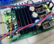
I also updated all the modules with 10uF Elna Silmic II on the TPA3255 inputs like in the picture below.
All muse caps = euphonic but I can hear the added distortion of Muse BP caps.
All silmic II = there's like a thick cloth in front of the speaker
Muse in frontend + silmic II before TPA3255 = bloom is retained with added smoothness of silmic II.
Attachments
Last edited by a moderator:
D
Deleted member 148505
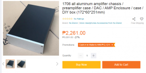
Nice case for my TICore260BTL, if used with external power supply.
1706 all aluminum amplifier chassis (172*60*251mm)
-------------------------------
Can a speakon connector be used as connector for DC umbilical cable?
I will create a companion power switch delay + softstart so that the amp will be safe when a 'live' umbilical cable is being connected.
1706 all aluminum amplifier chassis (172*60*251mm)
-------------------------------
Can a speakon connector be used as connector for DC umbilical cable?
I will create a companion power switch delay + softstart so that the amp will be safe when a 'live' umbilical cable is being connected.
Attachments
Can a speakon connector be used as connector for DC umbilical cable?
Hello
powerCON may be.
Best regards
Roger
D
Deleted member 148505
Hello
powerCON may be.
Best regards
Roger
Someone might connect powerCon AC on the amp.
I will use powerCon anyways, looks more fit for the job.
Lester, I'm playing with ti's LC filter tool you posted, and I'm not sure how you got 680nF cap for 682KL.
For Common mode, 4 Ohm speaker and 6,80 uH inductor, I see these results:
if C=0,68uF then f=74kHz, Q=0,632
if C=0,82uF then f=67,4kHz, Q=0,695
So with 820nF cap we can get better cut-off frequency and also more optimal damping factor (closer to 0,707). So why 680nF? What am I missing?
For Common mode, 4 Ohm speaker and 6,80 uH inductor, I see these results:
if C=0,68uF then f=74kHz, Q=0,632
if C=0,82uF then f=67,4kHz, Q=0,695
So with 820nF cap we can get better cut-off frequency and also more optimal damping factor (closer to 0,707). So why 680nF? What am I missing?
D
Deleted member 148505
Lester, I'm playing with ti's LC filter tool you posted, and I'm not sure how you got 680nF cap for 682KL.
For Common mode, 4 Ohm speaker and 6,80 uH inductor, I see these results:
if C=0,68uF then f=74kHz, Q=0,632
if C=0,82uF then f=67,4kHz, Q=0,695
So with 820nF cap we can get better cut-off frequency and also more optimal damping factor (closer to 0,707). So why 680nF? What am I missing?
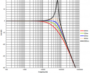
I was also looking at the peaking of 8 ohms load. It might affect the stability if peaking is too high.
Update: Verifying stability of our TICore260BTL (orig schematic) 51V DC rails module with VER2923-682KL. Inductor temp will not be a problem since the dissipation factor of it is low.
As pointed out by pppp, the 682KL has an ultra linear response which I already verified using THD measurements.
If proven stable. We will change the default inductor to VER2923-682KL
I have already tell you to try 7 mH coil Lester, good new that don't heat too much !
JLesterP said:I was also looking at the peaking of 8 ohms load. It might affect the stability if peaking is too high.
I understand, thanks. So, as I have 4 Ohm speakers, I will use at first the original 1uF output caps and 685KL, with only slightly underdamped Q=0,767. Maybe it will be better than 820nF and Q=0,695, as it will not damp some harmonics.
JLesterP said:Regarding SMPS300RS, I think the negative out terminal is too close to AC fuse, I'm afraid it might pickup some interferences. I'm also losing confidence on the 5mm pitch AC terminal.
Also they've dipped the whole board in insulating varnish / conformal coating bath, so the terminals including the faston tabs are now insulated lol.
I just checked my SMPS300RS 38V ordered from hifime on October, and it is exactly as you posted - everything sticky (PCB more, components only slightly) and dipped in varnish, even heatsinks and fastons, lol. But it can be scratched down from fastons, so ok for me.
As for that interference from AC fuse, do you think it will have some benefit when I partially shield the AC side?
You got the option C, the VER2923-103KL and LME49860 are included, so you don't need to buy inductors.
I also updated all the modules with 10uF Elna Silmic II on the TPA3255 inputs like in the picture below.
All muse caps = euphonic but I can hear the added distortion of Muse BP caps.
All silmic II = there's like a thick cloth in front of the speaker
Muse in frontend + silmic II before TPA3255 = bloom is retained with added smoothness of silmic II.
Ok so the best combo is Muse for front end and silmic for TPA input ?
Have you tested without front end cap ?
I also updated all the modules with 10uF Elna Silmic II on the TPA3255 inputs like in the picture below.
All muse caps = euphonic but I can hear the added distortion of Muse BP caps.
All silmic II = there's like a thick cloth in front of the speaker
Muse in frontend + silmic II before TPA3255 = bloom is retained with added smoothness of silmic II.
Don’t scoff, but I’m evaluating the use of WIMA MKS 1uF caps pre-opamp (had to mount them underneath the board; MKPs are better in signal paths but way too big) leaving the original MUSE bipolars pre-TPE3255 (since they are part of the PFFB build I didn’t want to change them). I’m just not a fan of Silmic IIs, sorry. All my reading tells me electrolytics shouldn’t be used in signal paths anyway and 1-4.7uF blocking caps are really all one needs on the input signal, no?
Currently rolling through op-amps to match everything in my system.
Regards,
Pete
D
Deleted member 148505
I have already tell you to try 7 mH coil Lester, good new that don't heat too much !
Yes I remember that you suggested it. Should have tested it before.
I only have 1 module here with 6.8uH, I've ordered more inductors so that I can test and compare modules with different configurations.
Using 6.8uH with 680nF might increase the output noise.
No, I'm using single supply for the opamps so the caps before opamps are mandatory.Ok so the best combo is Muse for front end and silmic for TPA input ?
Have you tested without front end cap ?
D
Deleted member 148505
I understand, thanks. So, as I have 4 Ohm speakers, I will use at first the original 1uF output caps and 685KL, with only slightly underdamped Q=0,767. Maybe it will be better than 820nF and Q=0,695, as it will not damp some harmonics.
Looks like 6.8uH + 1uF is better with our SMPS's switching frequency.
If we use smps with 65kHz switching freq (like lrs-350-36) it will amplify its residual in open load conditions. Haven't simulated zobel (220nF + 1 ohm) interaction though with the peaking.
Haha, yes don't remove the faston tab, the through hole's diameter in the PCB is smaller in diameter so I have to sandpaper grind my faston to slightly fit into it. I need to find faston tab with smaller pins.I just checked my SMPS300RS 38V ordered from hifime on October, and it is exactly as you posted - everything sticky (PCB more, components only slightly) and dipped in varnish, even heatsinks and fastons, lol. But it can be scratched down from fastons, so ok for me.
Hmm what shield and how will you place it? Can we check for the improvements without using an audio analyzer to check for mains harmonics?As for that interference from AC fuse, do you think it will have some benefit when I partially shield the AC side?
Attachments
D
Deleted member 148505
Don’t scoff, but I’m evaluating the use of WIMA MKS 1uF caps pre-opamp (had to mount them underneath the board; MKPs are better in signal paths but way too big) leaving the original MUSE bipolars pre-TPE3255 (since they are part of the PFFB build I didn’t want to change them). I’m just not a fan of Silmic IIs, sorry. All my reading tells me electrolytics shouldn’t be used in signal paths anyway and 1-4.7uF blocking caps are really all one needs on the input signal, no?
Currently rolling through op-amps to match everything in my system.
Regards,
Pete
As long as you don't notice the change in bass response, it's good.
Based on this calculator, looks like 2.2uF is better for bass response because the input impedance of our buffer is 10K ohms.
Coupling Capacitor Calculator by V-Cap
Silmic II makes the sound less transparent. Do you have a suggested 10uF electro cap for the pre-TPA3255 side?
D
Deleted member 148505
Thanks Lester for confirming my option C includes the inductors. Not sure how I managed to forget that!
Caps ordered however. Pana FC 1800uf
Nice
also don't forget the ATS heatsink.- Status
- Not open for further replies.
- Home
- Vendor's Bazaar
- Amplifier Modules and PCBs For Sale