D
Deleted member 148505
Calculating the dissipation of the HVIC in my JLAmp1000D shows that the IC needs heatsinking so that I can run it with higher osc. freq. while maintaining the reliability.
IR2110 does not heat much in my JLAmp1200D because the totem pole drivers took care of the gate drive.
IR2110 does not heat much in my JLAmp1200D because the totem pole drivers took care of the gate drive.
Nice design.......Are you going to sell the PCBs?
i would be very interested to purchase one. Can this amp drive a Cerwin Vega 12 or 15 inch woofer into 4 to 8 ohms?
Just curious if you have burned in your unit over several hours of playing time with any negative results?
thanks and GOD blesses us..
i would be very interested to purchase one. Can this amp drive a Cerwin Vega 12 or 15 inch woofer into 4 to 8 ohms?
Just curious if you have burned in your unit over several hours of playing time with any negative results?
thanks and GOD blesses us..
D
Deleted member 148505
Nice design.......Are you going to sell the PCBs?
i would be very interested to purchase one. Can this amp drive a Cerwin Vega 12 or 15 inch woofer into 4 to 8 ohms?
Just curious if you have burned in your unit over several hours of playing time with any negative results?
thanks and GOD blesses us..
Yes, eBay link is in the first page
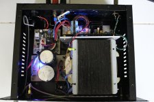
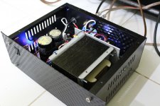
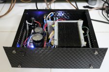
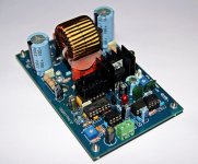
My amp can drive 2 ohm loads. This is the picture of my first build, I've been using this everyday since July and it never failed me specially on occassions/parties. It has +-65VDC unloaded rails and measured 500W into 2 ohms resistive load.
Regards,
Lester
Attachments
D
Deleted member 148505
Youtube video of power measurement of JLAmp1200D
JLAmp1200D Power Measurement at 2 ohms and 4 ohms dummy load - YouTube
Voltage sagging at 1.1KW full output power
JLAmp1200D Power Supply Voltage Sag at 1090W Full Power - YouTube
JLAmp1200D Power Measurement at 2 ohms and 4 ohms dummy load - YouTube
Voltage sagging at 1.1KW full output power
JLAmp1200D Power Supply Voltage Sag at 1090W Full Power - YouTube
D
Deleted member 148505
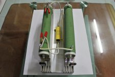
It's 2pcs Micrometals T106-6 with 30 turns of AWG18 solid wire. When stacked, it requires 3 more number of turns to get the equivalent inductance of stacked T106-2, but runs cooler ")
Note that material-6 (yellow, clear) is different than what you see on computer SMPS's which uses material-26 (yellow, white).
Note that material-6 (yellow, clear) is different than what you see on computer SMPS's which uses material-26 (yellow, white).
thanks for your answer
Hi
what about AMP power tester ?
plz give me the shematic and information for that
thanks
It's 2pcs Micrometals T106-6 with 30 turns of AWG18 solid wire. When stacked, it requires 3 more number of turns to get the equivalent inductance of stacked T106-2, but runs cooler
Note that material-6 (yellow, clear) is different than what you see on computer SMPS's which uses material-26 (yellow, white).
Hi
what about AMP power tester ?
plz give me the shematic and information for that
thanks
Hi
what about AMP power tester ?
plz give me the shematic and information for that
thanks
You put a resistive load on the amp and look for clipping on a scope.
D
Deleted member 148505
First time to listen to my JLAmp1000D in fullrange stereo, the sound is surprisingly good!
The treble is soft, not irritating and there's ambience and echo, soundstage is very wide. I'm very proud of it
Here's the youtube vid so that you'll have an idea of its sound. The camera audio sucks, the sound is wayy better in person of course. The background is also not clear because we live near a busy highway...
JLAmp1000D Stereo Sound Test - YouTube
D
Deleted member 148505
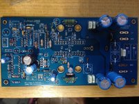
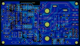
Trying the scaled down version of JLAmp1200D. I will be using IRFB5615 mosfets. The mosfets will use the same heatsink as the regulator (20degC/W)., The Totem Pole SMD buffers were bypassed by putting jumpers on PCB.
Target 300W @4ohms, "audiophile" sound
Will run at +-53VDC. By scaling down components, costs were almost cut to half compared to 1.2KW version
Target 300W @4ohms, "audiophile" sound
Will run at +-53VDC. By scaling down components, costs were almost cut to half compared to 1.2KW version
Attachments
D
Deleted member 148505
D
Deleted member 148505
D
Deleted member 148505
If the design is not finalized, is there any chance that you could make all the active devices heatsink mounted below the pcb like you did with the JLAmp1200/1000? That would set it apart from the LJM version, and all the others like it out there.
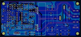
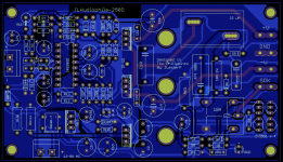
Thanks for the suggestion, we can provide better heatsink for the mosfets by mounting it below the pcb.
I also added 10A speaker protection circuit, it requires external 12-0VAC.
Size is now 2.8" x 4.9"
Attachments
Thanks for the suggestion, we can provide better heatsink for the mosfets by mounting it below the pcb.
I also added 10A speaker protection circuit, it requires external 12-0VAC.
Size is now 2.8" x 4.9"
Hi Lester,
I like this better because I can easily mount the board directly to a heat sink and that can be part of (e.g. the side of) the amp case, or on the back of a powered loudspeaker.
Any reason why you don't also do that with the 7812 regulator? The hole for it could be under R114, which could be repositioned slightly along with R113(?) in the corner of the board where they are located. That way all heat generation could be tied into the same heatsink that rejects heat to the outside of the case/enclosure...
-Charlie
D
Deleted member 148505
Hi Lester,
I like this better because I can easily mount the board directly to a heat sink and that can be part of (e.g. the side of) the amp case, or on the back of a powered loudspeaker.
Any reason why you don't also do that with the 7812 regulator? The hole for it could be under R114, which could be repositioned slightly along with R113(?) in the corner of the board where they are located. That way all heat generation could be tied into the same heatsink that rejects heat to the outside of the case/enclosure...
-Charlie
Hi Charlie,
With the right input voltage to feed the regulator, the LM7812 doesn't need heatsinking because the current which keeps the relay on will be quite low (around 50ma).
D
Deleted member 148505
D
Deleted member 148505
I'm selling my personal subwoofer amplifier module at a low price on eBay
7-10 days fast shipping.
Slightly Used IRFB4127 700W 2 Ohms JLAMP1000D Mono Amplifier Module IR2110 | eBay
7-10 days fast shipping.
Slightly Used IRFB4127 700W 2 Ohms JLAMP1000D Mono Amplifier Module IR2110 | eBay
- Status
- Not open for further replies.
- Home
- Vendor's Bazaar
- Amplifier Modules and PCBs For Sale