Cool! Just be careful with the power dissipation in the Maida Regulator if you use it in a variable power supply. This applies to any series element in a variable power supply, and in particular in high-voltage supplies. That P=V*I thing tends to bit you in places that should not be bitten.
Tom
Tom
Cool! Just be careful with the power dissipation in the Maida Regulator if you use it in a variable power supply. This applies to any series element in a variable power supply, and in particular in high-voltage supplies. That P=V*I thing tends to bit you in places that should not be bitten.
Tom
Was thinking of putting a DN2540 set as a current limiter ahead of the regulator.
That would work. One could also entertain the thought of implementing ranges on the supply. I.e. use different secondary taps to serve, say, 0-100; 100-200; 200-300; etc. volt outputs. Or get even fancier with synchronous rectification of the secondary voltage and regulate it (by controlling the four SCRs in the synchronous rectifier) to, say, 25 V above the desired output voltage. HP did that in the HP 6209B (great supply!).
You can get the schematics for the 6209B for not that much money from Artek Manuals: ArtekManuals | Your one stop shop for out of print test equipment manuals
One could also pre-regulate manually using a variac. There are many valid options.
Tom
You can get the schematics for the 6209B for not that much money from Artek Manuals: ArtekManuals | Your one stop shop for out of print test equipment manuals
One could also pre-regulate manually using a variac. There are many valid options.
Tom
I want to add a shutdown circuit to this circuit. I want to put a photofet optocoupler across R7 to kill the SET current, as per the LT3080 app sheet. This will make it totally floating and allow it to interface with the TTL error output of my bias regulator. The app note also shows a diode from the output to the set pin. Is all of this sounding "kosher" to you?
You will have some leakage to the output through D2 and R1+R10 (~1 MΩ). We're talking uA in most cases, so you can probably kill it by a resistor on the output of the regulator (maybe in series with a MOSFET to eliminate the power dissipated in the load resistor while the amp is operating).
I have not tried implementing a shutdown that way, but I think it will work.
Tom
I have not tried implementing a shutdown that way, but I think it will work.
Tom
The app note shows another FET as a pull down device on the output. I do not need 0.00V on the output as my intent is to avoid using a fuse to protect the output transformer. If I get a few uA leakage , that is OK, I just want to make sure I don't fry the optocoupler or the regulator or any thing else. I am taking the plunge and making myself learn LTspice so I can sim this idea and check voltages on C3 and R7 during startup and shutdown during fault conditions. Thanks for the vote of confidence.
why not use the SHDN pin?
The big question is what happens to the cascode when you do that. Somebody's gotta prevent the LT3080 from sudden death over-voltage conditions. I think it'd work - at least in steady-state. The big question is the transient conditions (power up/down). A simulation would reveal that - or most of that.
What pin is that?
I'm guessing the SET pin. Similar to the "Adding Shutdown" schematic on page 17 of the LT3080 data sheet.
Tom
I get that the set pin voltage is brought to zero for shutdown, not a problem, I want to know what the 1n4148 diode is doing. And in a 400V reg is there a chance of putting to much voltage on the SET pin or the transistor that bypasses it. Tom, when you said your amp sounded better with the regulator, were you going from original Maida to your circuit or, unregulated to your circuit?
I get that the set pin voltage is brought to zero for shutdown, not a problem, I want to know what the 1n4148 diode is doing.
It limits the voltage between OUT and SET during shutdown.
And in a 400V reg is there a chance of putting to much voltage on the SET pin or the transistor that bypasses it.
Absolutely. That's why I'd run a bunch of simulations before making any recommendations.
Tom, when you said your amp sounded better with the regulator, were you going from original Maida to your circuit or, unregulated to your circuit?
I've tried CLC, floating voltage regulator (similar to Joe Curico's design), and 21st Century Maida Regulator. I found improvements at every step.
Tom
replacement
can l replace STW11NK90Z with this
IPW80R360P7XKSA1 - MOSFET Transistor, N Channel, 13 A, 800 V, 0.31 ohm, 10 V, 3 V
https://my.element14.com/infineon/ipw80r360p7xksa1/mosfet-n-ch-800v-13a-to-247/dp/2771345
The specs look very close and same pin out. it is cheaper too.
thank you
kp93300
can l replace STW11NK90Z with this
IPW80R360P7XKSA1 - MOSFET Transistor, N Channel, 13 A, 800 V, 0.31 ohm, 10 V, 3 V
https://my.element14.com/infineon/ipw80r360p7xksa1/mosfet-n-ch-800v-13a-to-247/dp/2771345
The specs look very close and same pin out. it is cheaper too.
thank you
kp93300
Cool! Just be careful with the power dissipation in the Maida Regulator if you use it in a variable power supply. This applies to any series element in a variable power supply, and in particular in high-voltage supplies. That P=V*I thing tends to bit you in places that should not be bitten.
Tom
From Horowitz and Hill, the power (heat) across each MOSFET is divided by the number of devices:
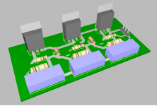
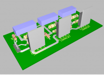
Attachments
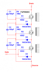
This should make it easier to select an FET Bigger soa because of less voltage.
Pointed out to me by reference to Fluke High Voltage power supplies in which it is used. Of course, they didn't have many (any?) MOSFETs back when the Fluke 341 was in production -- they used bipolars.
From Horowitz and Hill, the power (heat) across each MOSFET is divided by the number of devices:
Sure. Now you just need to get rid of ~250-500 W worth of heat (assuming you want 0.5 A or 1.0 A max output and regulation down to 0 V). That't why high-voltage supplies often use a switching pre-regulator.
Tom
Sure. Now you just need to get rid of ~250-500 W worth of heat (assuming you want 0.5 A or 1.0 A max output and regulation down to 0 V). That't why high-voltage supplies often use a switching pre-regulator.
Tom
Looking at the SOA of 3 heat-sinked TO-220 devices, at DC and 150V across each they should perspire, but not expire.
As you suggest, however, a variac on the front end! I also have a computer fan in my modified Heath IP-17
Attachments
Could a MOSFET such as the FDL100N50F from ON Semiconductor work in place of the STW11NK90Z?
It has a larger SOA, but comes at the cost of higher capacitance. Is there a good way to predict whether instability would result from the FDL100N50F or any other MOSFET that has a greater SOA?
It has a larger SOA, but comes at the cost of higher capacitance. Is there a good way to predict whether instability would result from the FDL100N50F or any other MOSFET that has a greater SOA?
- Home
- Vendor's Bazaar
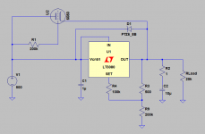
- 21st Century Maida Regulator