I place a resistive load on the supply equal to the minimum desired load. I use a big mosfet to switch in another resistor with the desired maximum load.
Yep. I do that as well. It doesn't give you a nice number for the output impedance, but it does tell you if the supply acts up under certain loads. It also gives you the transient response, thus, an idea of the phase margin or stability of the circuit.
After blowing up a chip amp I found that the turn on transient stuffs a spike through the OPT, back up the speaker output of the amp used to generate the test signal, so I switched to a tube amp, one of my SSE's.
Been there, done that -- at least as far as the semiconductor load goes. I find turn-on transients will destroy a MOSFET in a tiny fraction of a second. I actually used an op-amp to create a current source with a MOSFET driver. But after exploding a few expensive MOSFETs I decided that maybe this circuit wasn't optimal...
")
It didn't dawn on me to use a tube, but that's a really good idea. That should be a fairly rugged solution. I have some Sovtek 6L6'es that would be up to that task.
~Tom
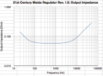
I used George's method for figuring the output impedance (thanks George!). I rigged the regulator to my 300B SET and cranked the signal generator. I measured the AC component of the B+ and the AC current drawn by the amp using a 10 ohm resistor in series with the OPT primary (that I have in there for easy bias point check anyway). Result's attached. Around 60 mOhm across most of the audio band. Not shabby...
I question the validity of the data below 100 Hz, though. I find it odd that the output impedance would be higher at DC than at mid band. But until I get a better test rig, this will have to do.
~Tom
I question the validity of the data below 100 Hz, though. I find it odd that the output impedance would be higher at DC than at mid band. But until I get a better test rig, this will have to do.
~Tom
Attachments
I question the validity of the data below 100 Hz, though. I find it odd that the output impedance would be higher at DC than at mid band. But until I get a better test rig, this will have to do.
~Tom
Try lowering the value of C5.
If you want to measure values below a a milliOhm, Kelvin Clips are almost a necessity, and you want to measure Zout as close to the regulator as possible.
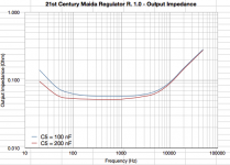
The simulated values I get with the "other LT LDO" are quite close to what I observe on the bench. Y-Axis is Ohms (milliOhms):
Attachments
Try lowering the value of C5.
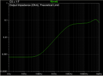
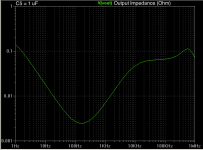
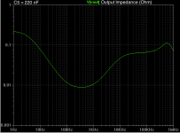
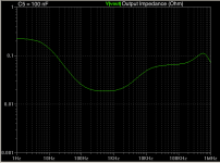
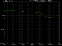
I beg to differ. Please stare at attached simulation results.
Graphs show the effects of varying C5 from 10 nF to 1 uF. I included C5 = 1 Farad as well to show the theoretical limit (ain't simulation wonderful).
It must have been a while since I looked at the output impedance in the simulation as it correlates very well with the behavior I'm measuring in the lab. The simulation predicts a mid-band output impedance in the low 10's of mOhm. I measure 60's of mOhm. I bet the difference is the routing resistance on the PCB as I measure at the output connector, not at the output of the regulator IC.
I'm considering increasing C5 to 220 nF, but I'll try it in the lab to see if it makes that much of a difference. I may just add a footprint for the bigger cap if it'll fit nicely on the board. I don't see a point of going much beyond that as the resistance of connectors and wires from the regulator to the load will negate the (marginal) improvement in Zout caused by a higher value of C5. Remote sensing (as jackinnj pointed out earlier) would be nice, but that's a project for a different day.
BTW, the Q of the complex pole pair at 570-ish kHz comes in at around 0.75~0.8 implying a phase margin around 60~65 degrees.
~Tom
Attachments
PCB is in fab. Pre-order available on my website.
I made a couple of additional tweaks to the board and sent it out for fabrication. The lead time is normally 8~10 days, so I expect to have boards available by the end of next week.
The boards are available for pre-order on my website (see my signature). I will ship as soon as they arrive.
~Tom
I made a couple of additional tweaks to the board and sent it out for fabrication. The lead time is normally 8~10 days, so I expect to have boards available by the end of next week.
The boards are available for pre-order on my website (see my signature). I will ship as soon as they arrive.
~Tom
I used George's method for figuring the output impedance (thanks George!). I rigged the regulator to my 300B SET and cranked the signal generator. I measured the AC component of the B+ and the AC current drawn by the amp using a 10 ohm resistor in series with the OPT primary (that I have in there for easy bias point check anyway). Result's attached. Around 60 mOhm across most of the audio band. Not shabby...
I question the validity of the data below 100 Hz, though. I find it odd that the output impedance would be higher at DC than at mid band. But until I get a better test rig, this will have to do.
~Tom
Awesome measurement, always firmly below 1ohm at all times, very nice. Should make a lot of amps sound much better!
Just an FYI: I'm still experimenting a little with the parts values. It dawned on me that the regulator needs to be able to supply the peak current drawn by the load and not just the DC quiescent current. Hence, I decreased R3 to 8.2 ohm (probably overkill, but parts were available). This leaves more voltage across the regulator IC so it maintains regulation even during peak load. I think a better solution is to use a 12 V zener diode, so D2 will change to 12 V. Also, D4 is actually optional with the cascode device I'm using (STW12NK95Z) as it has built-in back-to-back zeners. But if D2 changes to 12 V, using 12 V for D4 as well would be a logical choice to keep the BOM simple.
~Tom
~Tom
That's a really good question. I haven't tried connecting two supplies in series to form a split supply. But if they are fed by separate secondary windings and have separate rectifiers and reservoir caps, I would think that it would work. Beware that you cannot use a transformer with a center tap, though. The secondary windings have to be separate.
~Tom
~Tom
Thanks Tom,
What would you say is the max current it would safely take with the recommended heatsink? Would the limititing factor be the heatsink of the pass device? The pass device seems beefy enough for higher currents. I will be starting to built in a few weeks a 6528 PP amp (already have all the parts). It is class A and the stereo pair will pull 500ma at idle and 210V. I was planning to use a non regulated supply with large caps and choke input. Could save lots of space with your boards.
Thanks
Alfredo
Is there a pin-compatible negative regulator? If so, it's only a matter of switching polarity of polar parts and using a p-channel fet. I think I saw a 600V Ixys p-fet on mouser recently. I've built standard maidas with LM337 and they work fine and allow me to make split supplies from single center-tapped windings.
Is there a pin-compatible negative regulator? [...] I think I saw a 600V Ixys p-fet on mouser recently. I've built standard maidas with LM337 and they work fine and allow me to make split supplies from single center-tapped windings.
I'm not aware of a complimentary device, but then again... I haven't looked. But with the general trend in the industry to avoid negative supplies, I doubt one is available.
PMOS/PNP devices - especially high-voltage ones - are getting scarce. Digikey shows one 500+ V PMOS device.
I've built Maidas based on the LM337 as well. That works out. I've only used them for bias supplies, though. In future designs, I think I'll just do a zener stack with an emitter/source follower for bias supplies, though.
What would you say is the max current it would safely take with the recommended heatsink? Would the limititing factor be the heatsink of the pass device? The pass device seems beefy enough for higher currents. I will be starting to built in a few weeks a 6528 PP amp (already have all the parts). It is class A and the stereo pair will pull 500ma at idle and 210V. I was planning to use a non regulated supply with large caps and choke input. Could save lots of space with your boards.
You would save a lot of space and probably a fair bit of money as well by going the regulator route. And get better performance. What's not to like?
210 V out. Figure 25 V across the regulator, so you need 235 V across the reservoir cap. Figure the mains voltage varies +/-5 % resulting in +/-5 % variation on the secondary voltage. So you'd need (235*1.05)/1.25 = 197 V RMS from the secondary. I use 1.25 rather than the theoretical max of sqrt(2)=1.414 for the RMS-to-peak conversion as the conduction angle on the rectifier is non-zero.
So you'd get a 200 V trafo. Maybe 210 V.... Figure a worst case (for thermal dissipation) input voltage of 200*1.05*1.25 = 263 V resulting in 53 V across the regulator. At 500 mA, that's 53*0.5 = 26.5 W dissipated in the heat sink.
I prefer to not let my heat sinks run too hot. 60 degrees max.... So a 40 degrees rise above ambient (assuming an exterior heat sink). 40/26.5 = 1.5 deg/W. That would be the maximum thermal resistance of the heat sink I'd use.
I don't actually recommend a particular heat sink for the regulator. It's completely application dependent.
Note that heat sinks are generally specified at a temperature rise of 70 degrees C. At a more reasonable Trise, their thermal resistance is about 1.2x the number at 70 deg Trise. It makes a difference...
For heat sinks, I'd look at Heatsink USA. Personally, I'd use a 3" section of their 5.375" profile.
Hope this helps.
~Tom
Last edited:
- Home
- Vendor's Bazaar
- 21st Century Maida Regulator