How many here have been successful in using DimDim.s HiFiDuino Pro project?
TFT HiFiDuino Pro Project | Dimdim's Blog
I would like to use this to control my BIII Pro SE but I don't need the input select or volume control. I wanted to see if anyone has set it up and added or removed features.
TFT HiFiDuino Pro Project | Dimdim's Blog
I would like to use this to control my BIII Pro SE but I don't need the input select or volume control. I wanted to see if anyone has set it up and added or removed features.
I tried to get it to work with my BIII 9028 Pro DAC and could not. Tried another shield with a pro installing the chips, same thing. It could not see the DAC. I tired different power on scenarios with no luck.
Dimdim offered many suggestions and I appreciate that. I almost sent him the whole DAC to see if he could get it going. I wish I knew why I could not get it to work while others have.
I wish you well in your project!
Dimdim offered many suggestions and I appreciate that. I almost sent him the whole DAC to see if he could get it going. I wish I knew why I could not get it to work while others have.
I wish you well in your project!
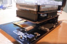
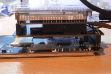
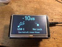
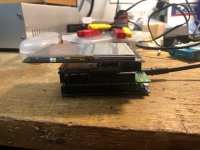
I was able to have someone take pics of a stacked working unit. This doesn't require a custom cable for the display. It was built for IR control. It requires the TFT shield from sainsmart. I'm waiting for the mail to deliver the shield.
Attachments
Last edited:
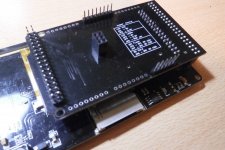
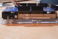
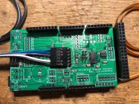
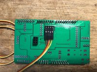
A small update... I was searching the sainsmart site for the screen shield and realized that they no longer pair the shield with the 4.3" screen, only the 5". I ordered it anyway just to see what came while emailing them asking if it works with the 4.3". They replied back this morning saying that the shield they stock will not work. This got me curious so I looked at the pick of the top of the shield from the known working unit and the version number and look of the shield are the same. However, I did notice that the shield I received was jumpered for 5V for both the LCD VCC and LCD LEDA+. The shield from the working unit is set for 3.3V. Could this be why the said it won't work?
I'm inclined to think this might work. I will jumper it for 3.3V and see if I can get something out of it. I've attached the pic of the working shield for those of you that go this route.
Also the headers used to stack this with DimDim's shield are female and have 12mm tails. I will try to source the headers this weekend to save the hassle for everyone else. What I can say so far is that mouser and digikey don't seem to stock this kind of part. What you can do is search for Arduino passthrough headers. Amazon seems to have a large selection. I've seen 12mm and 15mm tail lengths for the 1x8 headers there. Mouser does stock something from sparkfun and schmarterboard but the tail length is 10.5mm so I don't know if that's long enough at this point. The double row header is a bit tougher. So far Aliexpress is the only source I can find for a 2x16 with an 11mm tail. I see 2x20 from amazon so in a pinch this could be trimmed to fit I guess.
Lastly if the sainsmart combo doesn't work I have found this place
Arduino TFT LCD Display Touch Screen Shield,Tutorial,Library,Example
They have a 4.3" and a 5" with the required resolution and they come with a shield.
Attachments
Here are the headers. The should be here next week
https://www.amazon.com/gp/product/B0756KLNLX/ref=ppx_od_dt_b_asin_title_s00?ie=UTF8&psc=1
https://www.amazon.com/gp/product/B0756KLNLX/ref=ppx_od_dt_b_asin_title_s00?ie=UTF8&psc=1
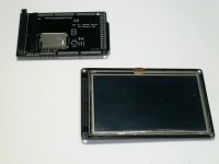
I have both the 4.3 and 5 inch displays working without the shield using the examples and libraries provided by the vendors.
here's the 5" instructions below. The 4.3 is a bit more involved. Buy the shield from sainsmart. They don't bundle it anymore and will tell you it does not work. It does!
4.3" instructions:
On the shield there are jumpers. You must remove the shorts for 5V and apply the shorts for 3.3V
To run a test what you need is here, just follow similaar steps in the 5" instructions:
101-50-150 - [[:Template:SainSmart Wiki]]
5" instructions:
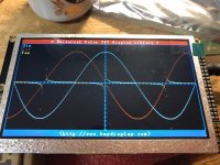
I got the no touch test pattern on the 5" display to work.
For those that are new (myself included), here's what I did.
Download the example file from buydisplay.com.
Extract it and the copy the UTFT folder located in Libraries-Examples_ER-TFTM050-4\Libraries into the Libraries folder in the Arduino folder under My Documents (Windows).
Open the .ino file located here Libraries-Examples_ER-TFTM050-4\Examples\No_Touch_GraphicTest
compile and upload the code
Remove the usb cable from the programming port
Assemble the shield, screen, and arduino together
Plug a 7-12 Vdc 1A or more power source into the power socket on the arduino board
It should display the test
here's the 5" instructions below. The 4.3 is a bit more involved. Buy the shield from sainsmart. They don't bundle it anymore and will tell you it does not work. It does!
4.3" instructions:
On the shield there are jumpers. You must remove the shorts for 5V and apply the shorts for 3.3V
To run a test what you need is here, just follow similaar steps in the 5" instructions:
101-50-150 - [[:Template:SainSmart Wiki]]
5" instructions:
I got the no touch test pattern on the 5" display to work.
For those that are new (myself included), here's what I did.
Download the example file from buydisplay.com.
Extract it and the copy the UTFT folder located in Libraries-Examples_ER-TFTM050-4\Libraries into the Libraries folder in the Arduino folder under My Documents (Windows).
Open the .ino file located here Libraries-Examples_ER-TFTM050-4\Examples\No_Touch_GraphicTest
compile and upload the code
Remove the usb cable from the programming port
Assemble the shield, screen, and arduino together
Plug a 7-12 Vdc 1A or more power source into the power socket on the arduino board
It should display the test
Attachments
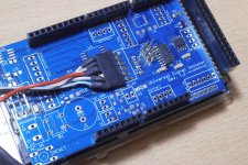
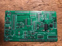
From the pictures of the working setup it appears you only need the following parts
C2 100n 1206
C3 100n 1206
C4 100n 1206
C10 100n 1206
R1 8.2K 1206
R2 2K 1206 pull-up resistor (optional)
R3 2K 1206 pull-up resistor (optional)
Q1 BC807, BC808 or other equivalent PNP SOT-23 TFT backlight control
U1 24LC256 SO-08 EEPROM chip
U2 Si8605 SOIC-16 I2C Isolator
I will install them tomorrow and then try to get the software working for the 4.3" display first
- Status
- This old topic is closed. If you want to reopen this topic, contact a moderator using the "Report Post" button.
- Home
- More Vendors...
- Twisted Pear
- DimDim's TFT HiFiDuino pro project