Hi,
this is a very interesting project. Keep posting your results")
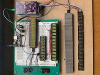
At the moment I test some display types for my DAC case.
As I am trying to learn some more programming I concentrate on the "hardware.side" of things for now.
But would need some C++ code for reading the sampling rate (and print it out),to put in Poni's fine code base. Which I am not capable of writing by myself (for now )
Regards
Branko
this is a very interesting project. Keep posting your results
At the moment I test some display types for my DAC case.
As I am trying to learn some more programming I concentrate on the "hardware.side" of things for now.
But would need some C++ code for reading the sampling rate (and print it out),to put in Poni's fine code base. Which I am not capable of writing by myself (for now
)Regards
Branko
Attachments
@Drone,
If you want to display the signal sample rate, it can be read and computed from DAC registers 66-69. This will be simple if you use the on-board 100MHz master clock in the Buffalo. However, if you wish to supply the Cronus clock as master - i.e. like 'true sync' - that will introduce uncertainty because the DAC will slave to frequencies that are multiples of either 44.1 or 48kHz. I do not see how the DAC chip would know which frequency it is being fed, although presumably the I2S renderer *will* know what frequency is specified in the music file. So for synchronous operation, if you want to display the signal frequency your C++ software will have to read some data from whatever digital source is creating the I2S. (I have that working with Python on the BBB - sorry but no clue with C++).
F.
Hi,
I have updated the Buffalo III ES9038Pro Software, there is new touch page to change settings, lock status and sample rate.
I have modified the sample rate calculation from dimdim.gr, i didnt test it myself but it seems to work.
Every setting displeyed in menu is actually read from register, so after writing register it is read again to confirm change.
The software is available to download on github with all libraries:
https://github.com/poninskit/TPA_Bu...06d576150e6014982185/BIII-ES9038Pro_1_0_9.zip
I have fiexed memory leak from v.1.0.9 (display sample rate) and improved refreshing and displaying Sample rate info:
https://github.com/poninskit/TPA_Bu...7c840afcf9b5fa2b257c/BIII_ES9038Pro_1.1.0.zip
https://github.com/poninskit/TPA_Bu...7c840afcf9b5fa2b257c/BIII_ES9038Pro_1.1.0.zip
Thank you for sharing! Also, beautiful case work in the photos!
In my last project I built-in a rotary encoder with the intention of making it multi-function so I could play with the settings in registers 28-29 for second order harmonics, and registers 30-31 for third order harmonics. Life has gotten in the way of finalizing that additional Python code, but I was expecting to discover that some distortion was euphonic. In your system, it would be one more display screen, and I imagine hours of 'fun' exploring the effects and value of those adjustments.
Best,
Frank
Hi Frank,
Playing with harmonics sounds very interesting, but it's also very advanced topic.
My intention was to write simple to follow code, easy to change and close to TPA Firmware, so only basic settings in simple to follow code are applied.
One example would be: there is a state design pattern in software development to make adding new screen pages very easy for ADVANCED programmer, but i didnt use it intensionaly, because its not easy to understand whats going on for "NON programmers", so at the end i decided to do it with switch-case and enum, which is not that nice, but easier to follow on the beginnig.
Another example would be, that i have took copy of Hifiduino/dimdim source code to determine and display sample rate which was 720(!) lines of code and i made from it 2 functions with 50 lines of code in total and single responsibilieties... one gets raw sample rate (fsr), second one returns human readable string.
char* DAC::getSampleRateString(uint32_t fsr)
{
R100_INPUT_STATUS r100;
r100.byte = readRegister(DAC_ADDRESS, 100);
//keep the strings equal length so no need to clr screen
if( r100.dop_is_valid == 1 || r100.dsd_is_valid == 1)
{
if(fsr > 461520) return (char*)"Invalid DSD ";
else if(fsr > 451000) return (char*)"44.8 MHz DSD";
else if(fsr > 225700) return (char*)"22.4 MHz DSD";
else if(fsr > 112000) return (char*)"11.2 MHz DSD";
else if(fsr > 56000) return (char*)"5.6 MHz DSD ";
else if(fsr > 28000) return (char*)"2.8 MHz DSD ";
else if(fsr > 1700) return (char*)"2.8 MHz DSD ";
else return (char*)"Invalid DSD ";
}
else if (r100.spdif_is_valid == 1 || r100.i2s_is_valid == 1)
{
if(fsr > 7690) return (char*)"Invalid SR ";
else if(fsr > 7675) return (char*)"768K PCM ";
else if(fsr > 7050) return (char*)"705.6K PCM ";
else if(fsr > 3835) return (char*)"384K PCM ";
else if(fsr > 3510) return (char*)"352.8K PCM ";
else if(fsr > 1910) return (char*)"192K PCM ";
else if(fsr > 1756) return (char*)"176.4K PCM ";
else if(fsr > 954) return (char*)"96K PCM ";
else if(fsr > 878) return (char*)"88.2K PCM ";
else if(fsr > 475) return (char*)"48K PCM ";
else if(fsr > 430) return (char*)"44.1K PCM ";
else if(fsr > 310) return (char*)"32K PCM ";
else return (char*)"Invalid SR ";
}
return (char*)" ";
}
Getting FSR is even easier:
DPLLNum |= readRegister(DAC_ADDRESS, 69); //0x45
DPLLNum <<= 8;
DPLLNum |= readRegister(DAC_ADDRESS, 68); //0x44
DPLLNum <<= 8;
DPLLNum |= readRegister(DAC_ADDRESS, 67); //0x43
DPLLNum <<= 8;
DPLLNum |= readRegister(DAC_ADDRESS, 66); //0x42
uint32_t fsr = ( DPLLNum * MCLK ) / 42940;
return fsr;
Thats the principles i have been follows while writing the soft.... so if anyone likes it, feel free to use and distribute it!
I have some BBB and Rasperry boards laying around and i thought of writing something in Python, but the point of havoing operating system running in the background with start and turn off routins holds me back. Microcontrollers are cheap and robbust, so you just switch them on and off.
Nice thing about BBB/Raspberry is that it could also run Streamer Audio Player like Roon or Volumio in the background.... so one gets DAC and Streamer! So maybe i will do somthing with linux board next time, but for now i prefere to spend time outside, have enough time in front of PC.
Best,
Tom
Last edited:
Greetings Tom,
Yes, good for you to get away from the keyboard. It is important, and so I do most of my hobby programming in winter, which can be very cold where i live.
On the topic of a combination streamer plus DAC, my most recent project was to build a group of 4 for family and myself. Using a Raspberry Pi, it is very simplified by using DietPi, which easily manages the Linux environment and updates, etc. You don't even need to worry about starting and stopping source programs because ALSA will only listen to one source at a time! You can simultaneously run as many interface programs (almost all are available in the DietPi package) as memory allows and just switch sources between, oh, spotify, squeezelite, MPD, etc. etc.! And of course, your phone can then become your control interface without custom code. I suggest a wired connection to the RPi because wifi is sometimes noisy. My python management code is not polished at the moment, so I'd be embarrassed to make it public - I was working on an HTML control panel but, as I mentioned, had to set that aside for now. Still, I'd be happy to send you the working code that is specific to the GPIO setup I use along with a custom isolation I/O interface board that I designed. It is all surface mount, though, so soldering is a challenge for the eyes. (I use a stereomicroscope for soldering) But I'm sure you could adapt the code to any other galvanic isolation source because GPIO is very simple.
All the best,
Frank
My RPi interface and isolator board is truly general purpose for low speed signals. It can power the RPi if you wish, but 'clean side' power must be separate. It accesses nearly every GPIO pin, 8 of which can supply an 8NPN Darlington IC (or the like) when higher current is required. I used USB output of the audio data from the RPi and convert it to I2S elsewhere (Amanero is one example). I believe Miero made a kernel to output I2S via GPIO on the RPi, but USB is quite flexible and simple. In addition, The RPI interface board from Twisted Pear appears to no longer be available.
Maybe this will give you some ideas... I believe some of the isolators and other composts are still in short supply.
Best,
Frank
.jpeg")
.jpeg")
Maybe this will give you some ideas... I believe some of the isolators and other composts are still in short supply.
Best,
Frank
Hi Frank,
Great job! Looks really nice, but didn't you also isolate I2C, so you don't need GPIOs anymore. You can just write the registers directly on es9038pro. I just put one small isolator for SDA/SCL (I2C) between the microcontroller and the dac and then just write the registers I want.
How do you control volume, do you have digital pot? But anyway, I really like the job.
I did something similar with soekris dam dac, i first used the gpios and digital pot, but switched to serial communication, this makes life actually way easier at the end.
Even though the soekris dac + anaview power amp ware supposed to be just the second system it turned really nice at the end... it's fairly simple, and it works with Arduino UNO!
I don't know what was more satisfying, putting the software together or the casework...I'm fairly pleased with result, some ppl can't even say it's DIY.


.jpg")
.jpg")
.jpg")
.jpg")
Great job! Looks really nice, but didn't you also isolate I2C, so you don't need GPIOs anymore. You can just write the registers directly on es9038pro. I just put one small isolator for SDA/SCL (I2C) between the microcontroller and the dac and then just write the registers I want.
How do you control volume, do you have digital pot? But anyway, I really like the job.
I did something similar with soekris dam dac, i first used the gpios and digital pot, but switched to serial communication, this makes life actually way easier at the end.
Even though the soekris dac + anaview power amp ware supposed to be just the second system it turned really nice at the end... it's fairly simple, and it works with Arduino UNO!
I don't know what was more satisfying, putting the software together or the casework...I'm fairly pleased with result, some ppl can't even say it's DIY.
That's mighty fine stuff! The appearances speak to your didication.
As for your question, there is quite a bit more to controling these rigs than just I2C to the DAC. I'm controling whether to run the DAC synchronously or async, controlling whether the RPi is the signal source or the DAC gets an external source (USB or SPDIF), controlling 115v power to a pair of Yamaha desk monitors, etc. For the interface I just made use of everything the RPi had available in addition to the I2C channels. That explains the little breadboards with ground and 3.3/5v nearby - easy to add something custom like the little board added on the front left on the one shown above. As I said, the original plan - yet to be completed - is full HTML control and in that case the rotary encoder will be used to incrementally adjust 2nd and 3rd harmonics instead of the default volume attenuation. Let the ear decide what it likes and then maybe go back and measure whatever that is!
Here are the boxes that the 4 streamer/DACs went into. All the standoffs thread cleanly into tapped holes in 3/16" base, the fronts are 1/4" brass with custom knobs, the tops are smoked acrylic with laser-cut ventilation and a bit of fun in the pattern, and the backs are 1/8" aluminum. My son takes credit for all of the metal and laser work. The sides are black granite - I did the stone work - laminated to acrylic for assembly. LEDs are momentary switches for simple front panel control.
Anyway, fun chatting and now back to my backlog keeping me from working on firmware...
Cheers,
F.

.jpg")
As for your question, there is quite a bit more to controling these rigs than just I2C to the DAC. I'm controling whether to run the DAC synchronously or async, controlling whether the RPi is the signal source or the DAC gets an external source (USB or SPDIF), controlling 115v power to a pair of Yamaha desk monitors, etc. For the interface I just made use of everything the RPi had available in addition to the I2C channels. That explains the little breadboards with ground and 3.3/5v nearby - easy to add something custom like the little board added on the front left on the one shown above. As I said, the original plan - yet to be completed - is full HTML control and in that case the rotary encoder will be used to incrementally adjust 2nd and 3rd harmonics instead of the default volume attenuation. Let the ear decide what it likes and then maybe go back and measure whatever that is!
Here are the boxes that the 4 streamer/DACs went into. All the standoffs thread cleanly into tapped holes in 3/16" base, the fronts are 1/4" brass with custom knobs, the tops are smoked acrylic with laser-cut ventilation and a bit of fun in the pattern, and the backs are 1/8" aluminum. My son takes credit for all of the metal and laser work. The sides are black granite - I did the stone work - laminated to acrylic for assembly. LEDs are momentary switches for simple front panel control.
Anyway, fun chatting and now back to my backlog keeping me from working on firmware...
Cheers,
F.
- Home
- More Vendors...
- Twisted Pear
- C++ Easy and Scalable Software for BIII38Pro