I have just finished building / upgrading my dual mono 9018+legato to 2x 9038+mercury and I must say it's quite an improvement!
My setup does not allow for a single DAC otherwise my speaker cable would become long. The signal runs to both dacs by Teleporters. I had expected I could run the boards in mono config with the default firmware which is not the case. Therefore I am now running one channel on both mercury boards instead of dual mono. I am curious to hear if there is any benefit since they already perform much better than my previous build. I do not have the equipment to flash the firmware but I will if it is worth the effort.
Does anybody have experience in running these boards in mono vs stereo config?
If there is no benefit, can I power just one side? I am using a Placid HDBP now with jumpers on the Mercury to power both sides.
Just remember that however you set the shunted current, that goes to warming the heat sinks, which are less efficient in a chassis than in open air. I’d be curious where Russ or Bryan set their Mercury supplies. With Legato I couldn’t hear any difference between 75mA vs. higher shunt amounts so 80 was my cold setting.
Is it correct to assume that if powering the L/R side of the Mercury with separate power supplies, that current draw would be halved? In other words, I would plan to provide 200mA to each of the L+, L-, R+ and R- channels shunting approximately 100mA on each channel (i.e. 200mA is the max current delivered, 100mA would be used and 100mA shunted). If I were powering L/R with one supply, I would plan to provide 300mA to the + channel and 300mA to the - channel, shunting approximately 100mA on each channel.
If I read you correctly, your two scenarios are not equivalent. It seems you will shunt twice as much current with the separate left and right supplies because you have 100mA each for L+, L-, R+, and R- for a total of 400mA. Whereas a single bipolar supply to both left and right will shunt 100mA each for L+&R+ and L-&R-. If you shunt 400mA, how much of that energy reserve would Mercury ever draw? 5-7% max?Is it correct to assume that if powering the L/R side of the Mercury with separate power supplies, that current draw would be halved? In other words, I would plan to provide 200mA to each of the L+, L-, R+ and R- channels shunting approximately 100mA on each channel (i.e. 200mA is the max current delivered, 100mA would be used and 100mA shunted). If I were powering L/R with one supply, I would plan to provide 300mA to the + channel and 300mA to the - channel, shunting approximately 100mA on each channel.
FWIW, I'm running in the latter configuration with one Placid HD 2.1 bipolar, shunting 90mA for plus and 90mA for minus and liking what I hear. ...not claiming to be correct or even optimal... IMO, a single Placid bipolar HD is a nice power supply. [PlacidHD is nowhere near to being a weak link in my particular system. Fixing the biggest weak link - room acoustics - has zero WAF!
") ].
].
Last edited:
Hi.I have just finished building / upgrading my dual mono 9018+legato to 2x 9038+mercury and I must say it's quite an improvement!
Could you compare both DACs in Vout mode?
Have you heard anything about 8ch 9038DAC?
Last edited:
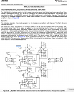
I have a basic question about the common mode servo that compares the common mode voltage at the transimpedance output to the common mode of the input:
While operating, would this servo correct for any abnormal disturbance in DAC chip differential output in which plus versus minus amplitudes significantly differ? In other words, would it 're-balance' to diminish or eliminate output of DC from the I/V stage?
...guessing it is different from the servo on page 10 of the LME49600 datasheet, but need to ask... TIA!
Frank
Attachments
Last edited:
Shunt Current
Hi francolargo,
I'm curious about your setting of 14.5V on the regulators. Do you know how much shunt current and CCS current you got when you set that up? I'm going to try it.
Also, I've put thumb wheels on my Buffalo IIISE to set the filter and the Bandwidth for DPLL. Setting the DPLL to minimum seemed to make things a bit cleaner. Mostly, I like the Apodizing filter. It's especially good when Brass sounds too Brassy.
Hugh
Among early observations, I was surprised by the saturation of transients with 9038/Mercury! Sometimes I wanted the drummers to just chill a bit.
Hi francolargo,
I'm curious about your setting of 14.5V on the regulators. Do you know how much shunt current and CCS current you got when you set that up? I'm going to try it.
Also, I've put thumb wheels on my Buffalo IIISE to set the filter and the Bandwidth for DPLL. Setting the DPLL to minimum seemed to make things a bit cleaner. Mostly, I like the Apodizing filter. It's especially good when Brass sounds too Brassy.
Hugh
Hi francolargo,
I'm curious about your setting of 14.5V on the regulators. Do you know how much shunt current and CCS current you got when you set that up? I'm going to try it.
Greetings Hugh,
That post was reporting on first impressions of new boards (Mercurys and PlacidHDs) with only a couple hours of use. I found that with time (more than a month) the transients seemed more reasonable - for whatever reason. Shunt current was about 100mA/channel, and Mercury was drawing about 175mA. After many hours of use, I turned the Mercury supply voltage back up to +&-15v with happy ears.
Also, I've put thumb wheels on my Buffalo IIISE to set the filter and the Bandwidth for DPLL. Setting the DPLL to minimum seemed to make things a bit cleaner. Mostly, I like the Apodizing filter. It's especially good when Brass sounds too Brassy.
I believe that here at diyAudio we tend to project our own experiences with particular components to their performance in other systems, where the upstream and downstream components can vary all over the map. ...not sure that is always helpful... As for filters, yes, I like the ability to change them to suit the (faults of?) the music source. In my system the two slow roll-off filters are best with the best quality recordings.
In comparing setups, I've found that with a teleporter sourcing the B3, it seems the DPLL can sit at the lowest setting regardless of sample rate. In contrast to that setup, with a USB (reclocking) source in a test layout, higher sample rates clearly sounded 'nicer' with DPLL set higher while lower sample rates were more clear at low DPLL settings. I think I have improved on that USB input layout but haven't evaluated yet for SQ.
Because of variables I've encountered where there is no guidance from ESS, TPA, nor other DIYers, I bought a piece of test equipment that I hope will answer some questions with graphic data. In the past, I've always just tinkered for best SQ. It might be fall before I can get the new analyzer running and get on the learning curve. In addition to tweaking the usual ESS Pro register settings using data along with SQ, I want to learn whether the built-in harmonic distortion algorithms are worth messing with...
Cheers,
Frank
Last edited:
Hi Frank,
Thanks for all of that. I too liked some of the other filters on a few higher quality recordings.
And I agree about upstream and downstream components. My system is a bit bright right now.
Good luck with the Analyzer and register tweaking. It sounds fascinating! I will stay tuned.
Hugh
Thanks for all of that. I too liked some of the other filters on a few higher quality recordings.
And I agree about upstream and downstream components. My system is a bit bright right now.
Good luck with the Analyzer and register tweaking. It sounds fascinating! I will stay tuned.
Hugh
Greetings Hugh,
That post was reporting on first impressions of new boards (Mercurys and PlacidHDs) with only a couple hours of use. I found that with time (more than a month) the transients seemed more reasonable - for whatever reason. Shunt current was about 100mA/channel, and Mercury was drawing about 175mA. After many hours of use, I turned the Mercury supply voltage back up to +&-15v with happy ears.
I believe that here at diyAudio we tend to project our own experiences with particular components to their performance in other systems, where the upstream and downstream components can vary all over the map. ...not sure that is always helpful... As for filters, yes, I like the ability to change them to suit the (faults of?) the music source. In my system the two slow roll-off filters are best with the best quality recordings.
In comparing setups, I've found that with a teleporter sourcing the B3, it seems the DPLL can sit at the lowest setting regardless of sample rate. In contrast to that setup, with a USB (reclocking) source in a test layout, higher sample rates clearly sounded 'nicer' with DPLL set higher while lower sample rates were more clear at low DPLL settings. I think I have improved on that USB input layout but haven't evaluated yet for SQ.
Because of variables I've encountered where there is no guidance from ESS, TPA, nor other DIYers, I bought a piece of test equipment that I hope will answer some questions with graphic data. In the past, I've always just tinkered for best SQ. It might be fall before I can get the new analyzer running and get on the learning curve. In addition to tweaking the usual ESS Pro register settings using data along with SQ, I want to learn whether the built-in harmonic distortion algorithms are worth messing with...
Cheers,
Frank
Thanks for this information!
I just powered up my Biiise 9038 with the Mercury and my inpression is also that it is quite bright with quite aggressive transients so nice to know that it will settle with burn in. It is very dynamic and impressive already.
I would like to reduce the gain a bit. Do I lower the resistors value on R 1 and 2 (I have 60r now)? I apologise sinse It has been explained already but I just want to be sure.
Thanks
Regards Chris
I would like to reduce the gain a bit. Do I lower the resistors value on R 1 and 2 (I have 60r now)?
Correct. Measure the replacements and match all 4 as closely as possible. The flexibility to do this is one thing I really like about the Mercury circuit.
Cheers!
But brightness and agresiveness scares me. Im wondering if burned in 9038 with tridentsr will be like mine 9018 just more resolving and dynamic??
I doubt any of us can answer your question. People actually listen differently so it is very hard to generalize what sounds different vs similar. ...add to that the age-related changes in high frequency sensitivity... OTOH, we do get accustomed to sound signatures of our rigs, and there are so many ways to tweak the sound.
Good luck!
My new Mercury has been running for 48+ hours now with my dual-mono Buffalo II. I had previously used both Legato and IVY for IV converter.
I tip my hat to Russ and Brian. The Mercury takes my DAC to a different level. The extension, resolution, tone/timber and soundstage all improved.
Because of the similar footprint and all, it was minimal work to substitute the IVY/Legato with the Mercury. I had some additional work due to my dual-Buffalo setup and had to improvise a bit to accommodate the shorter pin headers shipped with the Mercury.
Thanks for a wonderful product!
Attachments
Correct. Measure the replacements and match all 4 as closely as possible. The flexibility to do this is one thing I really like about the Mercury circuit.
Cheers!
I have 4 resistors matched in pairs. Should each matched pair be used on one channel as opposed to the same positions in each l/r channel?
Just wondering if anyone in here can give me some help..?
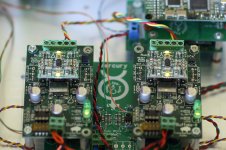
I've been building a dual mono dac using two Buffalo-IIIsePro38's. Taking one step at a time with SPDIF input to start, after using the firmware here https://github.com/twist...rmware/compare/dual-mono I now have a lock on each channel. However, no sound. I'm feeding the Mercury's to Ventus EZ's. Checking I noticed that SE and GND seem to be shorted on the Mercury, both sides of both boards. If I remember there was little to assemble. Just some caps and the Omron relays. I remember at the time wondering about the relays but using the markings on the board and a few photos I saw on line I though I had these lined up correctly. So perhaps i've fried some of the IC's? At this point I'm considering ordering another couple of Mercury's but I'd rather know what the problem is before doing that. The resistance across ROSE is 4R8 if that helps.
Taken from the omron pdf "Use the Relay as soon as possible after opening the moistureproof package. (As a guideline, use the Relay within one week at 30°C or less and 60% RH or less.) If the Relay is left for a long time after opening the moisture-proof package, the appearance may suffer and seal failure may occur after the
solder mounting process. To store the Relay after opening the moisture-proof package, place it into the original package and sealed the package with adhesive tape."
The humidity over here (Bangkok) is mostly 60% (to say nothing of temperatures) and at the time I soldered the board it was probably 75%. I work in an aircon room but its not left on all the time. So damage to the relays is certainly a possibility if I opened the package and did not seal it (I can't recall).
![rmCdNKb"]](/community/proxy.php?image=http%3A%2F%2F%5BURL%3D%22https%3A%2F%2Fibb.co%2FrmCdNKb%22%5D&hash=b9616758832baff16e2b56c51e72ccbd)
So my question is, as the resistsnce across GND and SE is 0R2, might this be the relays or have I done something else daft?[/URL]
I've been building a dual mono dac using two Buffalo-IIIsePro38's. Taking one step at a time with SPDIF input to start, after using the firmware here https://github.com/twist...rmware/compare/dual-mono I now have a lock on each channel. However, no sound. I'm feeding the Mercury's to Ventus EZ's. Checking I noticed that SE and GND seem to be shorted on the Mercury, both sides of both boards. If I remember there was little to assemble. Just some caps and the Omron relays. I remember at the time wondering about the relays but using the markings on the board and a few photos I saw on line I though I had these lined up correctly. So perhaps i've fried some of the IC's? At this point I'm considering ordering another couple of Mercury's but I'd rather know what the problem is before doing that. The resistance across ROSE is 4R8 if that helps.
Taken from the omron pdf "Use the Relay as soon as possible after opening the moistureproof package. (As a guideline, use the Relay within one week at 30°C or less and 60% RH or less.) If the Relay is left for a long time after opening the moisture-proof package, the appearance may suffer and seal failure may occur after the
solder mounting process. To store the Relay after opening the moisture-proof package, place it into the original package and sealed the package with adhesive tape."
The humidity over here (Bangkok) is mostly 60% (to say nothing of temperatures) and at the time I soldered the board it was probably 75%. I work in an aircon room but its not left on all the time. So damage to the relays is certainly a possibility if I opened the package and did not seal it (I can't recall).
So my question is, as the resistsnce across GND and SE is 0R2, might this be the relays or have I done something else daft?[/URL]
OK so I have replaced the relays....still the same.
There is a popping sound at power up, silence and then at power off a sound like a needle sketching a vinyl lp, then a low murmer.
I have measured the resistance between SE and GND at only around 1 ohm when powered up which is slightly higher than the 0.2 ohms I'm seeing when powered down. That just sounds wrong. On the IVY I had about 22 ohms between SE and GND.
Oh and I used the 60 ohm resistors for R1_1 etc.
- Home
- More Vendors...
- Twisted Pear
- Introducing Mercury - Achieving escape velocity.