Since the IVY also can be used as a balanced headphone amp I wonder how the Mercury fares in this regard?
Cheers
Thomas
Exactly the same.
") You can use it like IVY-III in that respect.
You can use it like IVY-III in that respect.Really as long as you live within the confines of the OPA1632 datasheet you will be just fine driving any headphone. The absolute max output current of the OPA1632 is 150ma - I would never try to push it much beyond 100ma though - so you just have to plan based on your intended load. For high impedance cans I give myself some extra voltage gain - for low impedance cans I sometime reduce the gain but usually leave it alone. If your cans need more than 100ma or so then I would use a separate headphone amp. I only have a couple of pair that need more - and they are special cases.
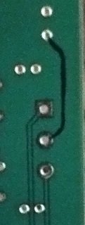
Instead of adding a jumper (which is a totally valid solution as well IMHO..) you could just scrape the green solder mask over the ground plane next to the ground pin and use a blob of solder to make the connection.
Indeed you could! We just thought the jumper method was easier for most folks to execute. Either method is fine.
When will the Version 1.1 of the Mercury be purchased?
I'm worried that adding a 12mm jumper at the right-channel balanced ground will cause unbalance between the left and right channels, affecting sound quality. If jumpers are added to both left and right channels, the problem is smaller.
No - the jumper absolutely wouldn't effect quality
Balanced signals don't work like that. GND is not really part of the signal for a balanced output - all that really matters is that the shield has a single path back to GND.In any case - 1.1 boards are ordered but it will probably be a couple of weeks before they are ready - in the meantime I would not let the jumper stop you.
Cheers!
Russ
Last edited:
..... - in the meantime I would not let the jumper stop you.
Cheers!
Russ
It isn't stopping me! Should we flatten the wire so it thinks it's a trace?
Happy Thanksgiving to all!
Can you tell me the length of BUFFALO-IIISE PRO and Mercury IV individually? I need to arrange a drill hole in the housing.
How can I connect BUFFALO-IIISE PRO with Mercury IV?
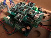
This should get you going.
You simply solder the female 3 pin headers to bottom of the b3se-pro and the male headers to the top of the Mercury. Then you simply mount the B3SE-Pro on top of the mercury.
It will look like the attached pic (this is a mercury during initial testing in my test rig).
Cheers!
Russ
Attachments
So with the servos there is no DC offset or common mode DC offset from the balanced or single ended outputs correct?
I just want to make sure I don't feed my amps any DC offset
Well virtually none - there will still be a very small amount (generally a few mv) because the opamps themselves have some tiny input offset - and even at .1% resistors are not perfectly matched
The servo reduces the offset to very close to zero - but if you want absolutely no DC your only choice is to AC couple I am reading ~1mv offset at the SE output and a bit less at the balanced outputs.
Cheers!
Russ
For the multichannel version of the III Pro dacs, would we need to get 4 of the Mercury IV boards to do 8 channels or do you have a different idea up your sleeve?
Of course you could use 4 Mercury (and that would sound great) - but I have something more fitting for the application in the works
ok, sounds good. I think the servos in my amp can handle that.Well virtually none - there will still be a very small amount (generally a few mv) because the opamps themselves have some tiny input offset - and even at .1% resistors are not perfectly matched
I am reading ~1mv offset at the SE output and a bit less at the balanced outputs.
Cheers!
Russ
If I order today should I get V1.0 or V1.1 (corrected pcb)?
Depends on how soon you want to start enjoying the music
They will both sound the same.- Home
- More Vendors...
- Twisted Pear
- Introducing Mercury - Achieving escape velocity.