I use the last Volumio from volumio.org (Jun 11, 2017) with "Botic" as output device. For debugging ...
Are you able to address the BBB via the command line? If not, debugging will be hit-or-miss. If the problem is Volumio then you could be wasting time trying other things. I suggest using the Linux command ‘speaker-test’ and/or ‘aplay’.
speaker-test(1) - Linux man page
aplay(1) - Linux man page
If the commands don’t seem to execute correctly, then use a botic distribution without Volumio until they do work.
Frank
Last edited:
Thanks for your replies!!
So far the LCDPS seems to suffice. The output stays at 5V.Is the output of the LCDPS staying at 5V? It may be running out of current. At some point you might want to replace the small value resistor (I think it's 1R) on the LCDPS with a jumper - so that you don't have a huge voltage drop after it. Only do this if it is actually running out of steam
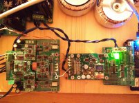
You may also want to use a more stout supply like the Centaur. Centaur was purpose designed for higher current loads like this application.
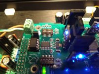
I installed both LEDs. The A_Mute LED just lights up briefly when turning the Buffalo on. After that both stay out.Also you should install the indicator LEDs on the B3SE-pro - so you can see if things are locking and/or auto-mute is on.
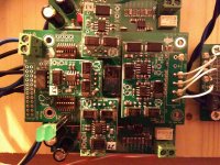
I have completely overseen this! While trying to change it, it fell off :-/. I just put in the important positions 6-8 again. The others should be fine with the "off" position. I also checked the on/off state for all positions.Also - make sure you set the dip switches for PCM/DSD input.
See here:
GitHub - twistedpearaudio/Buffalo-III-SE-Pro-On-Board-Firmware
Switch 1 - Position 1 should be off.
speaker-test gives me:Are you able to address the BBB via the command line? If not, debugging will be hit-or-miss. If the problem is Volumio then you could be wasting time trying other things. I suggest using the Linux command ‘speaker-test’ and/or ‘aplay’.
But still no music playing...volumio@volumio:~$ speaker-test
speaker-test 1.0.28
Playback device is default
Stream parameters are 48000Hz, S16_LE, 1 channels
Using 16 octaves of pink noise
Rate set to 48000Hz (requested 48000Hz)
Buffer size range from 16 to 786432
Period size range from 8 to 393216
Using max buffer size 786432
Periods = 4
was set period_size = 196608
was set buffer_size = 786432
0 - Front Left
Time per period = 10.136222
0 - Front Left
Time per period = 10.239882
0 - Front Left
Time per period = 10.239842
0 - Front Left
Time per period = 10.239874
[...]
Attachments
uname -a
aplay -lLinux volumio 4.8.13-botic7-rc3 #1 PREEMPT Sat Dec 10 01:35:51 CET 2016 armv7l GNU/Linux
for i in /sys/module/snd_soc_botic/parameters/*; do echo $i=$(cat $i); done**** List of PLAYBACK Hardware Devices ****
card 0: Botic [Botic], device 0: external botic-hifi-0 []
Subdevices: 1/1
Subdevice #0: subdevice #0
/sys/module/snd_soc_botic/parameters/blr_ratio=64
/sys/module/snd_soc_botic/parameters/clk_44k1=22579200
/sys/module/snd_soc_botic/parameters/clk_48k=24576000
/sys/module/snd_soc_botic/parameters/dai_format=16385
/sys/module/snd_soc_botic/parameters/dsd_format_switch=1
/sys/module/snd_soc_botic/parameters/ext_masterclk=3
/sys/module/snd_soc_botic/parameters/pinconfig=default
/sys/module/snd_soc_botic/parameters/serconfig=MDR-
Thanks. This seems to be OK.
I guess that clock signal is correctly routed into BBB, because speaker-test was playing (printing messages).
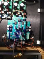
I suggest you to check voltages on DCK, D1 and D2 pins (relative to their GNDs) on the input and output of the Cronus. Be sure to use matching GND, as they are not connected.
The best option would be check them with an oscilloscope, but a decent multimeter might "work" too.
Check first with AC milivoltmeter. There might be some non-zero voltage - a signal present.
Have you tried your B3 with another digital source than BBB? For example with SPDIF optical receiver. Just to be sure, that B3 works well.
I guess that clock signal is correctly routed into BBB, because speaker-test was playing (printing messages).
I suggest you to check voltages on DCK, D1 and D2 pins (relative to their GNDs) on the input and output of the Cronus. Be sure to use matching GND, as they are not connected.
The best option would be check them with an oscilloscope, but a decent multimeter might "work" too.
Check first with AC milivoltmeter. There might be some non-zero voltage - a signal present.
Have you tried your B3 with another digital source than BBB? For example with SPDIF optical receiver. Just to be sure, that B3 works well.
Thanks for your help!
I think I found the mistake: I had no u.fl connectors available and my local electronic store also didn't had them, so I just used a simple cable totally forgetting that the u.fl connector has two poles. I realized it when you said I should measure to their respective GNDs. That should be it, right? I just ordered the connectors. Sorry...
I think I found the mistake: I had no u.fl connectors available and my local electronic store also didn't had them, so I just used a simple cable totally forgetting that the u.fl connector has two poles. I realized it when you said I should measure to their respective GNDs. That should be it, right? I just ordered the connectors.
Sorry...That should be it, right? I just ordered the connectors.
Doubtful - u.fl connectors should be fine, but they are not required.
There is already a gnd connection - so no need for uFL.
I am pretty concerned by state of your switches... This is a first for me - I have never seen them destroyed like yours before You will need to be sure that the signal each switch controls is actually low (0V - or closed) or high (3.3V or open) manually - fortunately you have a header there for that.
Cheers!
Russ
I am pretty concerned by state of your switches... This is a first for me - I have never seen them destroyed like yours before
You will need to be sure that the signal each switch controls is actually low (0V - or closed) or high (3.3V or open) manually - fortunately you have a header there for that.Cheers!
Russ
Doubtful - u.fl connectors should be fine, but they are not required.
Damn, I thought that was itThere is already a gnd connection - so no need for uFL.
.The top just fell of when I moved one of the switches. When I measure at the GPIO Pins I get the following values starting from the upper left (with respect to the GPIO label):I am pretty concerned by state of your switches... This is a first for me - I have never seen them destroyed like yours before
1: 3.3, 0.0, 0.0, 0.0, 0.0, 3.3 (V)
2: 3.25, 0.006, 1.6, 3.5, 0.001, 0.0 (V)
1: 3.3, 0.0, 0.0, 0.0, 0.0, 0.0, 0.0, 0.0, 0.0, 0.0, 1.5, 3.3 (V)
2: 3.3, 0.0, 3.3, 3.3, 3.3, 3.3, 3.3, 0.0, 0.0, 0.0, 3.3, 3.3 (V) - an the mute LED lighted up briefly when I measured the last three values.
Sorry, I cannot see how the 2 x 8 switches related to the GPIO pins. However, I ensured with a multimeter that the switches that are "on" are actually connected. That seems fine.
I did as you instructed. I cannot see a difference to to power connection. So, there seems to be no signal from the Cronus (?).I suggest you to check voltages on DCK, D1 and D2 pins (relative to their GNDs) on the input and output of the Cronus. Be sure to use matching GND, as they are not connected.
No, unfortunately I have no other source available.Have you tried your B3 with another digital source than BBB? For example with SPDIF optical receiver. Just to be sure, that B3 works well.
One more thing: I measure 10-30mV at the Mercury outputs when its turned on.
Any ideas left? :-/
Hi,
I'm having challenges with digital noise from the BIII-SE-Pro28 board.
When operating either with I2S or SPDIF input then after several minutes then digital noise appears randomly in both channels
Se picture of dip setting for the I2S input. The Sync is ON all the time. I also measured that there are constantly 5V on the main input.
When I turn off the DAC and turn it on again then it works ok for some minute before the digital noise appears again. Unfortunately I can't attach a sound file from this site does not recognize the format.
If I go back to my old BIII then there is no noise and it works nice with same setup including the Voltage regs
Any clues to what is wrong? I have tried a second BIII-SE-Pro board and same problem!!!
Attachments
Neslo
What are those regs on the BIII-SE-Pro28 board.
Hi,
I'm having challenges with digital noise from the BIII-SE-Pro28 board.
What are those regs on the BIII-SE-Pro28 board.
Hi Russ, Are you still planning on releasing sync mode firmware (when finalized) via PIC sales at TPA?
+1!
Greg in Mississippi
Sounds to me like one of your regs (probably 1.2V) is running out of current or getting too hot. This wouldn't happen on the older DACs - they use a lot less current. Also we recommend running that supply at ~1.25V as opposed to 1.2V.
Cheers!
Russ
Hi Russ
Thks..I measured the voltage across the VDD and it was only 1.1v. After connecting external PSU with 1.2v then plays fine 😀👍
What are those regs on the BIII-SE-Pro28 board.
It is Newclassd UWB2 regulators
Get
Some TPA regs, those new class D are not anywhere close and likely the source of your problems.
It is Newclassd UWB2 regulators
Some TPA regs, those new class D are not anywhere close and likely the source of your problems.
+1!
Greg in Mississippi
+1 (and if there is a dual mono version, I would order another DAC on top)...
Some TPA regs, those new class D are not anywhere close and likely the source of your problems.
What's do you mean that they are not anywhere close?
Yes the Newclassd have a voltage drop more than 1.7v (5-3.3) but now I have them external and it works fine
Damn, I thought that was it
The top just fell of when I moved one of the switches. When I measure at the GPIO Pins I get the following values starting from the upper left (with respect to the GPIO label):
1: 3.3, 0.0, 0.0, 0.0, 0.0, 3.3 (V)
2: 3.25, 0.006, 1.6, 3.5, 0.001, 0.0 (V)
1: 3.3, 0.0, 0.0, 0.0, 0.0, 0.0, 0.0, 0.0, 0.0, 0.0, 1.5, 3.3 (V)
2: 3.3, 0.0, 3.3, 3.3, 3.3, 3.3, 3.3, 0.0, 0.0, 0.0, 3.3, 3.3 (V) - an the mute LED lighted up briefly when I measured the last three values.
Sorry, I cannot see how the 2 x 8 switches related to the GPIO pins. However, I ensured with a multimeter that the switches that are "on" are actually connected. That seems fine.
I did as you instructed. I cannot see a difference to to power connection. So, there seems to be no signal from the Cronus (?).
No, unfortunately I have no other source available.
One more thing: I measure 10-30mV at the Mercury outputs when its turned on.
Any ideas left? :-/
So, the u.fl connectors just arrived, but - as you already said - this did not change anything. Still no music playing.
What else could I do? Can anyone interpret the voltage measurements? I take every hint
Attachments
Last edited:
in...
Noise and impedance performance. The ADM 715x IC well outperforms the DEXA regs. The DAC will sound better with the TPA regs, I personally guarantee it, discrete is not always better.
What's do you mean that they are not anywhere close?
Yes the Newclassd have a voltage drop more than 1.7v (5-3.3) but now I have them external and it works fine
Noise and impedance performance. The ADM 715x IC well outperforms the DEXA regs. The DAC will sound better with the TPA regs, I personally guarantee it, discrete is not always better.
- Home
- More Vendors...
- Twisted Pear
- Introducing the Buffalo III-SE-Pro 9028/9038