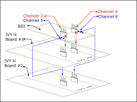
BIII with 2 Ivy III
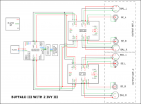
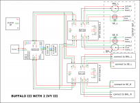
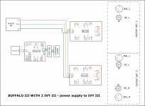
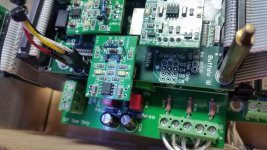
Is it possible to connect the BIII with 2 IVY III like these?
1) with 2 parallels outputs
2) with 1 output but from 2 IVY outputs
3) parallel power supply from Placid
Is it possible to connect the BIII with 2 IVY III like these?
1) with 2 parallels outputs
2) with 1 output but from 2 IVY outputs
3) parallel power supply from Placid
Attachments
1) Yes
2) Maybe, but I would not
3) Yes
Also note, the four-channel S/PDIF module and Sidecar. Those are designed for the 8-channel Buffalo-III.
It would be better to use the 4:1 Mux module for multiple S/PDIF sources for the BIIIse. Switching between S/PDIF and I2S is handled on the DAC using the IP_S header.
Thanks, Brian.
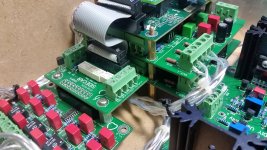
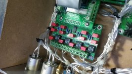
I am using the Buffalo-III with the four-channelS/PDIF module and the Sidecar. The Sidecar is not connecting to any input but is chained to the 4-channel/S/PDIF module. It is there for future expansion.
Right now I have connected both the IVY3 to the B-III to the same channel as per the drawing.
The problems I encounter :
1) Noise distortion from both speakers. I noticed that the output from the left channel is measured at 0.46V as compared to the 77.5mV from the right channel.
2) CD Transport signal dropping every 5 to 10 seconds. I am using the shigaclone and it has no problem with another DAC. The B-III has no problem with my media player.
3) First one second of signal is lost - eg. for some songs, the first second opening of the song is missing. The BIII just locked in a second late. (This issue is already there before I install the second board.)
Do I need to set any jumpers on the B-III or set the switch position?
Appreciate any suggestions and help.
Thank you.
Attachments
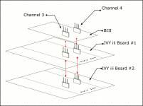
Hi Brian, no, I'm not using 2 IVY's to drive the output in parallel. I am not sure if it will work so I drop that idea. I'm driving 4 pairs of outputs from the 2 IVYs as drawn in the first diagram on the above post.
When one IVY is used, there's no distortion but signal drop from cd transport still occurs. When 2 IVYs are stacked up as shown in the drawing above, the distortion sets in. Do I need to connect the other IVY to another channel on the B-III board?
I do not know why is the very first half to one second lock onto the cd transport's signal is lost and also the dropped signals every 5 to 10 seconds.
Thanks.
Last edited:
When you connect to IVYs to a single pair of outputs, you are having the available current to each output stage. This is one factor in the distortion.
The additional current draw is likely also causing the dropouts.
I think you would be better off with a single IVY. You should have no problem driving multiple outputs from a single pair of IVY outputs.
The additional current draw is likely also causing the dropouts.
I think you would be better off with a single IVY. You should have no problem driving multiple outputs from a single pair of IVY outputs.
Hi
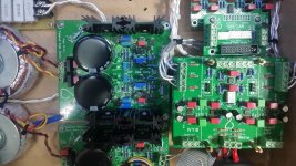
I have now lost the right channel. I am using only one IVY board now.
My measurement with the CD transport connected and playing:
Placid HD for B-III
Start = 5.36V
After half hour = 5.22V
Shunt : 68.1mV
Placid HD-BP for IVY
Left Channel : 14.90V
Shunt : 62.7mV
Right Channel : 14.97V
Shunt : 66.9mV
The dropouts still occurs, now at 30 or 40 seconds each time. The distortion is gone but the 1st second of the signal is still missing. This 1st second missing signal only happened with the media player. It is perfectly okay with the CD transport.
Now, I have adjusted the shunt current while with the cd transport connected and playing for 20 minutes but still the dropouts occurs, sometimes frequent, sometimes not so :
Placid HD-BP
Left :
Shunt : 189.5mv
CSS : 346.5mV
Output : 14.83V
Right :
Shunt : 189.1mV
CSS : 344.1mV
Output : 14.73V
I don't know which firmware I am using.
Placid HD-BP
Left :
Shunt : 189.5mv
CSS : 346.5mV
Output : 14.83V
Right :
Shunt : 189.1mV
CSS : 344.1mV
Output : 14.73V
I don't know which firmware I am using.
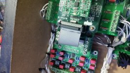
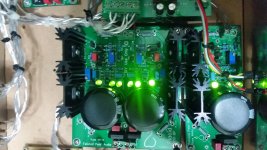
More pictures.
Another question : How does the 'mute' operate? It seems that when no signal is lock on, the mute Led lights up but as soon as a signal is detected, the 'mute' led is off even if you selected another none signal input.
Thanks again.
Another question : How does the 'mute' operate? It seems that when no signal is lock on, the mute Led lights up but as soon as a signal is detected, the 'mute' led is off even if you selected another none signal input.
Thanks again.
Attachments
Hmm - it might be time to rule out a problem with the IVY-III...
I would test it by removing it from the rest of the circuit and connecting the inputs to GND. Then power it up with +/- 15V as usual and check all of the outputs. They should be very close to 0V. Also check that none of the ICs are getting overly hot. They will be warm - but should not be hot. If one of the OPA1632 is really hot it will need to be replaced (it likely has an internal short from some damage).
You could also swap out the IVY-III and test the one you have not used yet.
- Status
- This old topic is closed. If you want to reopen this topic, contact a moderator using the "Report Post" button.
- Home
- More Vendors...
- Twisted Pear
- 2 ivy iii for B3