Thanks largely to the persistence of Miero and his work on Botic, the capabilities of BBB-based music players are steadily expanding. However, it is unreasonable to expect Miero to anticipate the preferences or needs of every builder. This thread is intended as a place to share our individual solutions to various control and integration scenarios - from the routine to very specialized. I hope you will consider showing off what you have done with your own hardware and software. I will do the same with my very basic efforts as progress is made. I'm keeping it as simple as possible using bash and python. Be forewarned, my approach here will be as a beginner whose knowledge is gained from trial-and-error with heavy emphasis on the error! 
To start, let me go 'pie in the sky' and present a couple of possibilities for controllers that I am thinking about but with which i have zero experience. The ideas and possibilities seem really transformative - really worth learning about. These control methods use mobile device apps (iOS and Android) that allow one to construct their own "remote controls" for lots of different kinds of devices. (Who doesn't have a retired smartphone that could be put into service?) Here, I'm thinking of controlling things like system inputs and outputs (e.g., a TPA OttoII), volume, other play parameters, etc. This can be done from a SSH command line, but these controller programs are truly multifunctional. I don't want to duplicate the many excellent controllers for MPD or Squeezelite, but how about controlling other equipment or room lighting from the same hand-held device? The internet of things is arriving.
NetIO is a fairly well-developed platform with an online design application for configuring controllers. A variety of widgets can be incorporated into the controls, like buttons, switches, sliders, displays, etc. Advanced controllers can be multi-page and programmed to change pages as the functions require. If I'm not mistaken, the control panel can also display information gathered from the 'slave' device. The interface between the mobile control device and the slave device is limited. Quoting the developer:
Blynk is the other DIY controller App. This is less expensive and is perhaps more broadly applicable, being employed in "lower-level" device control tasks as well as at the level of Linux development boards. If I'm not mistaken, there is javascript server code that runs on Rpi but that has not been ported to BBB. Both NetIO and Blynk host user forums, and it seems the level of discussion is more technical with Blynk. The Q/A is harder for me to understand. So I don't know which of the two systems would be easier to use after gaining working knowledge.
Are any readers experienced with either of these two systems? What is your advice?
Because my BBB is wired and not wifi, opening a TCP port doesn't worry me. So I will probably try NetIO using TCP enabled by Python scripts. I will report back when I know more. I will also share the interrupt and control scripts that are now about 50% done - along with photos, of course!
...looking forward to your thoughts and ideas...
To start, let me go 'pie in the sky' and present a couple of possibilities for controllers that I am thinking about but with which i have zero experience. The ideas and possibilities seem really transformative - really worth learning about. These control methods use mobile device apps (iOS and Android) that allow one to construct their own "remote controls" for lots of different kinds of devices. (Who doesn't have a retired smartphone that could be put into service?) Here, I'm thinking of controlling things like system inputs and outputs (e.g., a TPA OttoII), volume, other play parameters, etc. This can be done from a SSH command line, but these controller programs are truly multifunctional. I don't want to duplicate the many excellent controllers for MPD or Squeezelite, but how about controlling other equipment or room lighting from the same hand-held device? The internet of things is arriving.
NetIO is a fairly well-developed platform with an online design application for configuring controllers. A variety of widgets can be incorporated into the controls, like buttons, switches, sliders, displays, etc. Advanced controllers can be multi-page and programmed to change pages as the functions require. If I'm not mistaken, the control panel can also display information gathered from the 'slave' device. The interface between the mobile control device and the slave device is limited. Quoting the developer:
Code:
NetIO does not support SSH connections. It is only TCP sockets , UDP or HTTP and
HTTPS.
However, there is a project from simi-chan http://netioapp.com/de/projects/681
that enables the execution of bash commands via NetIO without a special
self-programmed server.
@kushal_mehta51 hostnames work, so if you have a dyndns address and the router
configured correctly, you can just use the dyndns address to connect from the
internet.
Blynk is the other DIY controller App. This is less expensive and is perhaps more broadly applicable, being employed in "lower-level" device control tasks as well as at the level of Linux development boards. If I'm not mistaken, there is javascript server code that runs on Rpi but that has not been ported to BBB. Both NetIO and Blynk host user forums, and it seems the level of discussion is more technical with Blynk. The Q/A is harder for me to understand. So I don't know which of the two systems would be easier to use after gaining working knowledge.
Are any readers experienced with either of these two systems? What is your advice?
Because my BBB is wired and not wifi, opening a TCP port doesn't worry me. So I will probably try NetIO using TCP enabled by Python scripts. I will report back when I know more. I will also share the interrupt and control scripts that are now about 50% done - along with photos, of course!
...looking forward to your thoughts and ideas...
I have a question for anybody with an electronics background.
Background:
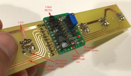
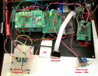
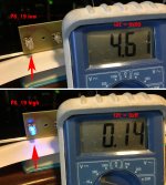
On my BBB/Hermes/Cronus build, I wanted front panel indicator LEDs for the system inputs and outputs. Plus, I wanted momentary buttons to control the BBB via GPIO inputs. I decided to use small buttons with incorporated LEDs - the LED is not controlled by the switch. To drive the LEDs from BBB, I used BS270 FETs as suggested by Derek Molloy and connected the gate to the GPIO header. Power to the LED came from the 3.3v supply on the Hermes prototype area.
Problem:
All was well until I decided to reboot the system by merely cutting power and letting the LiPO battery shut down the BBB. After that, all 5 of the BS270s were shorted. I can't imagine what happened to the FETs because all of the voltages and currents are supposedly well within the normal operating range. In order to avoid this kind of headache in the future, I need to understand what happened. Any suggestions? Any remedies?
Thanks in advance!
Frank
Background:
On my BBB/Hermes/Cronus build, I wanted front panel indicator LEDs for the system inputs and outputs. Plus, I wanted momentary buttons to control the BBB via GPIO inputs. I decided to use small buttons with incorporated LEDs - the LED is not controlled by the switch. To drive the LEDs from BBB, I used BS270 FETs as suggested by Derek Molloy and connected the gate to the GPIO header. Power to the LED came from the 3.3v supply on the Hermes prototype area.
Problem:
All was well until I decided to reboot the system by merely cutting power and letting the LiPO battery shut down the BBB. After that, all 5 of the BS270s were shorted. I can't imagine what happened to the FETs because all of the voltages and currents are supposedly well within the normal operating range. In order to avoid this kind of headache in the future, I need to understand what happened. Any suggestions? Any remedies?
Thanks in advance!
Frank
Attachments

For your application, I thing is more easy to use the ULN2803.
Cheers
http://www.ti.com/lit/ds/symlink/uln2803a.pdf
Cheers
An externally hosted image should be here but it was not working when we last tested it.
http://www.ti.com/lit/ds/symlink/uln2803a.pdf
For your application, I thing is more easy to use the ULN2803.
Thanks for the suggestion! Today I got a ULN2003 for testing. The internals seem the same as the part you referenced. Obviously the BS270 FETs are more fragile than I imagined! Regards, Frank
Thanks again for the suggestion, @smanz! I am using an older analogue of the ULN2003 - a MCT1413 - and it is working perfectly. A battery-powered shutdown did no harm (with a breadboard setup). I will make a new switch/LED interface board and then continue working on the scripts that will run the various switch functions. When the details are all working, I will post the setup and code in this thread.
I read one piece of advice regarding Rpi that seems worth passing along to those who may be customizing their BBB-based systems. It may be obvious to many, but it is this: For GPIO outputs that are controlling other circuits, it is best to choose pins that are inputs by default. This prevents a disorderly activation of the external circuits by default output pins that could occur during the boot process. As a final step in preparing the BBB to run, the default input pins can be re-assigned as outputs, set high or low, and the chances of frizzing the BBB will be lower. Under Botic, those include unclaimed GPIO pins P8_7 to P8_10 (input, high) and P8_11 to P8_19 (input, low).
I read one piece of advice regarding Rpi that seems worth passing along to those who may be customizing their BBB-based systems. It may be obvious to many, but it is this: For GPIO outputs that are controlling other circuits, it is best to choose pins that are inputs by default. This prevents a disorderly activation of the external circuits by default output pins that could occur during the boot process. As a final step in preparing the BBB to run, the default input pins can be re-assigned as outputs, set high or low, and the chances of frizzing the BBB will be lower. Under Botic, those include unclaimed GPIO pins P8_7 to P8_10 (input, high) and P8_11 to P8_19 (input, low).
I am working on the question of digital volume control for the three BIIIse DACs in my system - one stereo DAC for bass, one for midrange, and one for high frequencies. Ideally, it would be great to have individual control of volume for each DAC. [...tweak the driver blend at different volumes]
I2C directly to the ES9018 works, but is limited to two channels. Using a buss extender seems inconvenient. Thus, I would like more information about the stock micro controller on the Buffalo, which is the default potentiometer-controlled method.
Questions:
How many taps or volume levels does the micro controller implement in the ES9018?
How much current does each micro controller draw through the external potentiometer?
Bottom line: I am wondering if it is feasible or inadvisable to use one I2C-controlled multi-channel digital pot to drive each onboard micro controller on each Buffalo board.
It´s easy. You can use this IC 4 Channel I2C Multiplexer
This is the modified Hifiduino (Arduino) code to write registers. Some comments are in spanish, but is easy to understand. I have conected four buffalos. Two of this with addres jumper mounted and another two without jumper. Are in quad mono configuration.
// The default mode is for the address 0x48 to be the left chip
void writeSabreLeftReg(byte regAddr, byte regVal)
{
Wire.beginTransmission(0x70); //Llamo al multplexador
Wire.write(0x04); //Selecciono canal 0
Wire.endTransmission();
Wire.beginTransmission(0x48); //Hard coded to the the Sabre/Buffalo device address
Wire.write(regAddr); // Specifying the address of register
Wire.write(regVal); // Writing the value into the register
Wire.endTransmission();
Wire.beginTransmission(0x70); //Llamo al multplexador
Wire.write(0x05); //Selecciono canal 1
Wire.endTransmission();
Wire.beginTransmission(0x48); //Hard coded to the the Sabre/Buffalo device address
Wire.write(regAddr); // Specifying the address of register
Wire.write(regVal); // Writing the value into the register
Wire.endTransmission();
}
// In dual mono, sometimes different values are written to L and R chips
#ifdef DUALMONO
void writeSabreRightReg(byte regAddr, byte regVal)
{
Wire.beginTransmission(0x70); //Llamo al multplexador
Wire.write(0x04); //Selecciono canal 0
Wire.endTransmission();
Wire.beginTransmission(0x49); //Hard coded to the the Sabre/Buffalo device address
Wire.write(regAddr); // Specifying the address of register
Wire.write(regVal); // Writing the value into the register
Wire.endTransmission();
Wire.beginTransmission(0x70); //Llamo al multplexador
Wire.write(0x05); //Selecciono canal 1
Wire.endTransmission();
Wire.beginTransmission(0x49); //Hard coded to the the other Sabre/Buffalo device address
Wire.write(regAddr); // Specifying the address of register
Wire.write(regVal); // Writing the value into the register
Wire.endTransmission();
}
More information about register functions is in Hifiduino sketch.
Regards
Thanks for the suggestions, Miero and Smanz!
Brian let me know that the firmware uses 255 steps of 0.5 dB, which seems excellent for being controlled by a digipot with 8 bit resolution. So I will continue with learning about I2C reads/writes, and see if I can make it work well enough.
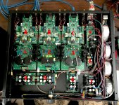
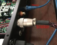
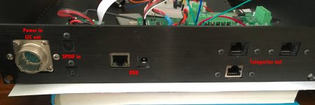
I do have a problem caused by planning the hardware without all the information about I2C that I needed. The system will use 2 boxes - one plain rack box and one smaller, nicer chassis that will show. At the moment most of the wiring is still very untidy! All of the power supplies (1-9 in the photo) and the DACs (A-C) are in the rack box. The BBB and associated hardware will be separate in the smaller chassis, with a multi-function cable between them. I only gave myself 4 wires for communication between the two boxes. The PCA9544A seems like a great solution but I wonder if 4 wires are enough? Vdd and Vss could come from a BIII...
I will continue learning and testing the 1 channel 8-bit digipot. If it seems like a workable solution, then I will try a 4 channel version inside the rack box. But if it doesn't work well, I will drop the idea and try a different approach.
Best,
Frank
Brian let me know that the firmware uses 255 steps of 0.5 dB, which seems excellent for being controlled by a digipot with 8 bit resolution. So I will continue with learning about I2C reads/writes, and see if I can make it work well enough.
I do have a problem caused by planning the hardware without all the information about I2C that I needed. The system will use 2 boxes - one plain rack box and one smaller, nicer chassis that will show. At the moment most of the wiring is still very untidy! All of the power supplies (1-9 in the photo) and the DACs (A-C) are in the rack box. The BBB and associated hardware will be separate in the smaller chassis, with a multi-function cable between them. I only gave myself 4 wires for communication between the two boxes. The PCA9544A seems like a great solution but I wonder if 4 wires are enough? Vdd and Vss could come from a BIII...
I will continue learning and testing the 1 channel 8-bit digipot. If it seems like a workable solution, then I will try a 4 channel version inside the rack box. But if it doesn't work well, I will drop the idea and try a different approach.
Best,
Frank
Attachments
Thanks for the suggestions, Miero and Smanz!
The PCA9544A seems like a great solution but I wonder if 4 wires are enough? Vdd and Vss could come from a BIII...
,Frank
If you mount PCA9544 in Buffalo chassis, you only need two wires, SDA and SCL. You can obtain 3,3v Vdd from buffalo, and Vss is common ground between buffalo and clean side of hermes.
Regards
If you mount PCA9544 in Buffalo chassis, you only need two wires, SDA and SCL. You can obtain 3,3v Vdd from buffalo, and Vss is common ground between buffalo and clean side of hermes.
Regards
You will need a common ground as well.
I have been investigating the NetIO utility for iOS as a way to make custom remote controllers for the BBB. A TCP socket server in Python is published for the RPi. I am hopeful it will be not too much work to adapt this python server script from RPi to the BBB. I believe the BBB version will require that a port be opened and bound to the IP. ...but I have yet to maintain a connection to the iOS app.
Any thoughts on adapting the above-linked netIO server script to communicate with the BBB?
Any thoughts on adapting the above-linked netIO server script to communicate with the BBB?
NetIO Remote Control - proof of concept
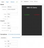
Notwithstanding how much work has already been done to make the BBB a stunning little audio renderer, I think significant potential remains untapped. Even if only in terms of flexibility and convenience. That's mostly what this thread is about. I am a noob with both Linux and Python. Undeterred, I just started hacking with the NetIO remote control application and the demo script that was written for RPi GPIO control. ...partial success! As I see it, the potential seems more than enough to continue developing this avenue to wirelessly and remotely control a BBB-based audio appliance.
What: NetIO is an iOS/Android app that can control smart digital hardware via a TCP or web interface from a smartphone or tablet. It can use either Python or Java server code, but it has been applied mostly to the RPi rather than the BBB. In addition to sending commands, the mobile device can display status messages from the remote server (the BBB).
Why: The app is very well conceived for flexibility, power, and convenience. In addition, the open-source Python server script can be customized to eliminate bloat - just run the code that is essential to your tasks.
A modest start adapting the server script to the BBB: OK, I have not gotten two-way communications working yet, just control from my iPad to the BBB. But the needed configuration for two-way can't be thaaat difficult, and the app developer supports a help forum. As mobile apps go, $9 is a bit pricey, but the amount of work in this system is significant and once 'we' have clean server modules running under Botic/BBB, it will literally take only minutes to construct a kick-butt remote.
The steps to make a remote are:
A) There is no free demo - buy the app.
B) Use the web based interface configuration tools to create the remote's screen. There are many widgets to choose from that include options for the properties and configuration parameters of your choosing. Save that to your account and...
C) Open the mobile app and synch your saved remote(s) to the device.
D) Program the server script on the BBB to respond appropriately on the various commands &/or interrupts.
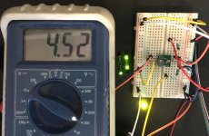
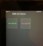
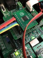
My demo: From my iPad I asked the BBB to do three things using a simple button press - 1) control GPIO outputs on the BBB P8 header, 2) execute a shell script, and 3) write control values to an I2C slave. Piece of cake for all 3. The GPIO control was visible as an LED circuit turning on or off. The shell script was one of a few that I am writing to act as subroutines for the overall control of my audio appliance - it showed up on the terminal. The I2C slave device is a 5K digital potentiometer that I am playing with but ultimately will not use - I'll send I2C directly to each of my Buffalo boards. ...no matter - this is just proof of concept for the control app. The attached photos show a screen grab of the web-based UI designer, how the 2-button screen looks on my iPad, the 5K digipot on the breadboard, and the evidence that the Python server script in the BBB was executing correctly. Pretty fun for a couple hours of pure hacking.
The rough/unfinished server script adaptation: Again, this is the modified product of the NetIO developer, available online for use in the RPi. Your improvements & suggestions very much appreciated! You will want/need to install the Adafruit_BBIO.GPIO library, which makes working with the GPIO header much simpler. I will continue working with it and learning about this app and control system, and will post any significant advances here.
All the best,
Frank
Odd! Lines 12 and 14 are not reading correctly on my screen. Correct syntax inside parenthesis is: quote - pin number - quote - comma - space - GPIO - period - direction/value
Notwithstanding how much work has already been done to make the BBB a stunning little audio renderer, I think significant potential remains untapped. Even if only in terms of flexibility and convenience. That's mostly what this thread is about. I am a noob with both Linux and Python. Undeterred, I just started hacking with the NetIO remote control application and the demo script that was written for RPi GPIO control. ...partial success! As I see it, the potential seems more than enough to continue developing this avenue to wirelessly and remotely control a BBB-based audio appliance.
What: NetIO is an iOS/Android app that can control smart digital hardware via a TCP or web interface from a smartphone or tablet. It can use either Python or Java server code, but it has been applied mostly to the RPi rather than the BBB. In addition to sending commands, the mobile device can display status messages from the remote server (the BBB).
Why: The app is very well conceived for flexibility, power, and convenience. In addition, the open-source Python server script can be customized to eliminate bloat - just run the code that is essential to your tasks.
A modest start adapting the server script to the BBB: OK, I have not gotten two-way communications working yet, just control from my iPad to the BBB. But the needed configuration for two-way can't be thaaat difficult, and the app developer supports a help forum. As mobile apps go, $9 is a bit pricey, but the amount of work in this system is significant and once 'we' have clean server modules running under Botic/BBB, it will literally take only minutes to construct a kick-butt remote.
The steps to make a remote are:
A) There is no free demo - buy the app.
B) Use the web based interface configuration tools to create the remote's screen. There are many widgets to choose from that include options for the properties and configuration parameters of your choosing. Save that to your account and...
C) Open the mobile app and synch your saved remote(s) to the device.
D) Program the server script on the BBB to respond appropriately on the various commands &/or interrupts.
My demo: From my iPad I asked the BBB to do three things using a simple button press - 1) control GPIO outputs on the BBB P8 header, 2) execute a shell script, and 3) write control values to an I2C slave. Piece of cake for all 3. The GPIO control was visible as an LED circuit turning on or off. The shell script was one of a few that I am writing to act as subroutines for the overall control of my audio appliance - it showed up on the terminal. The I2C slave device is a 5K digital potentiometer that I am playing with but ultimately will not use - I'll send I2C directly to each of my Buffalo boards. ...no matter - this is just proof of concept for the control app. The attached photos show a screen grab of the web-based UI designer, how the 2-button screen looks on my iPad, the 5K digipot on the breadboard, and the evidence that the Python server script in the BBB was executing correctly. Pretty fun for a couple hours of pure hacking.
The rough/unfinished server script adaptation: Again, this is the modified product of the NetIO developer, available online for use in the RPi. Your improvements & suggestions very much appreciated! You will want/need to install the Adafruit_BBIO.GPIO library, which makes working with the GPIO header much simpler. I will continue working with it and learning about this app and control system, and will post any significant advances here.
All the best,
Frank
Code:
#!/usr/bin/env python
# -*- coding: utf-8 -*-
import asyncore
import socket
import select
import Adafruit_BBIO.GPIO as GPIO
import time
import subprocess  # will be used in the future to call 'subroutine' scripts
import smbus

# misc. GPIO setup as needed to address pins
GPIO.setup("P8_19", GPIO.OUT)  # render problem?
GPIO.output("P8_19", GPIO.LOW)  # render problem?
GPIO.setup("P8_18", GPIO.IN)  # render problem?

# setup to test I2C control of digipot
bus = smbus.SMBus(1)
bus.write_byte_data(0x2e, 0x04, 0xff)
bus.write_byte_data(0x2e, 0x00, 0x00)

SWITCH1 = "P8_18"

class Client(asyncore.dispatcher_with_send):
    def __init__(self, socket=None, pollster=None):
        asyncore.dispatcher_with_send.__init__(self, socket)
        self.data = ''
        if pollster:
            self.pollster = pollster
            pollster.register(self, select.EPOLLIN)

    def handle_close(self):
        if self.pollster:
            self.pollster.unregister(self)

    def handle_read(self):
        receivedData = self.recv(8192)
        if not receivedData:
            self.close()
            return
        receivedData = self.data + receivedData
        while '\n' in receivedData:
            line, receivedData = receivedData.split('\n',1)
            self.handle_command(line)
        self.data = receivedData

    def handle_command(self, line):
        if line == 'LED1 on':
            self.send('on\n')
            # GPIO.output("P8_19", GPIO.HIGH)
            subprocess.call("./BBB_in.sh", shell=True)
            bus.write_byte_data(0x2e, 0x00, 0xff)
        elif line == 'LED1 off':
            self.send('off\n')
            GPIO.output("P8_19", GPIO.LOW)
            bus.write_byte_data(0x2e, 0x00, 0x00)
            print 'set led 1 off'
        elif line == 'get status':
      #      print 'Input Status:', GPIO.input(SWITCH1)
      #      if GPIO.output("P8_19", GPIO.HIGH):
      #          self.send('on\n')
      #          print 'Read GIOP 0 result On'
      #      else:
                self.send('off\n')
      #          print 'Read GIOP 0 result Off'
                # ende if
        else:
            self.send('unknown command\n')
            print 'Unknown command:', line

class Server(asyncore.dispatcher):
    def __init__(self, listen_to, pollster):
        asyncore.dispatcher.__init__(self)
        self.pollster = pollster
        self.create_socket(socket.AF_INET, socket.SOCK_STREAM)
        self.bind(listen_to)
        self.listen(5)

    def handle_accept(self):
        newSocket, address = self.accept()
        print "Connected from", address
        Client(newSocket,self.pollster)

def readwrite(obj, flags):
    try:
        if flags & select.EPOLLIN:
            obj.handle_read_event()
        if flags & select.EPOLLOUT:
            obj.handle_write_event()
        if flags & select.EPOLLPRI:
            obj.handle_expt_event()
        if flags & (select.EPOLLHUP | select.EPOLLERR | select.POLLNVAL):
            obj.handle_close()
    except socket.error, e:
        if e.args[0] not in asyncore._DISCONNECTED:
            obj.handle_error()
        else:
            obj.handle_close()
    except asyncore._reraised_exceptions:
        raise
    except:
        obj.handle_error()

class EPoll(object):
    def __init__(self):
        self.epoll = select.epoll()
        self.fdmap = {}
    def register(self, obj, flags):
        fd = obj.fileno()
        self.epoll.register(fd, flags)
        self.fdmap[fd] = obj
    def unregister(self, obj):
        fd = obj.fileno()
        del self.fdmap[fd]
        self.epoll.unregister(fd)
    def poll(self):
        evt = self.epoll.poll()
        for fd, flags in evt:
            yield self.fdmap[fd], flags


if __name__ == "__main__":
    pollster = EPoll()
    pollster.register(Server(("",8192),pollster), select.EPOLLIN)
    while True:
        evt = pollster.poll()
        for obj, flags in evt:
            readwrite(obj, flags)
Odd! Lines 12 and 14 are not reading correctly on my screen. Correct syntax inside parenthesis is: quote - pin number - quote - comma - space - GPIO - period - direction/value
Attachments
Last edited:
It´s easy. You can use this IC 4 Channel I2C Multiplexer
@smanz, thanks again for another great suggestion! Because I have to learn everything as I go, it seemed like too much trouble to multiplex the bus. But now I see it is an elegant solution and it is working perfectly with all 3 DACs at address 0x48. The PCA9544 is on the 5th board layer in this tightly organized chassis.
Because I have a separate BIIIse for the bass, midrange, and tweeter channels, it will be fun to experiment whether controlling the digital volume of each DAC sounds similar to old-style bass, mid, and treble preamp controls! ...much to do still on this project but it is all rewarding. When Botic 6 is released (thanks in advance for your continued work, Miero!) there will be even more fun in the area of implementing and controlling new sources for the BBB and the digital crossover that it runs.
Cheers!

Attachments
Muting the s9018
Question for Miero or Brian or whomever:
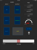
I'm making progress with the NetIO controller programming. The volume slider in NetIO is nicely done!
In configuring an I2C mute function, is there any reason NOT to set bit one of register 10 (to cf)? It gives full silence, of course, and nicely returns to the original volume when returned to value ce. However, I don't recall reading that others have programmed that register in their controllers. Are there any 'unadvertised' disadvantages of truly muting vs. lowering the volume registers to 0? I want to be nice to these chips!
TIA,
Frank
Question for Miero or Brian or whomever:
I'm making progress with the NetIO controller programming. The volume slider in NetIO is nicely done!
In configuring an I2C mute function, is there any reason NOT to set bit one of register 10 (to cf)? It gives full silence, of course, and nicely returns to the original volume when returned to value ce. However, I don't recall reading that others have programmed that register in their controllers. Are there any 'unadvertised' disadvantages of truly muting vs. lowering the volume registers to 0? I want to be nice to these chips!
TIA,
Frank
Here is a prototype wifi remote control for the BBB that I made in NetIO. It is on the same iPad that will control the music library. Most of it is proving easy to code, though the cute little 'Source Freq.' gauge will require some patience... And of course, the spdif input controls must await Botic 6.
Attachments
Last edited:
hi francolargo,
in botic6 with enabled i2c control of es9018 within kernel driver the dac will be muted (by using mute flag in that register) everytime unless it is playing or muted by user request. so it will be unmuted just before start of play and muted right after the end of playback.
but I have to figure out how to integrate control of multiple DACs into ALSA control system.
- Status
- This old topic is closed. If you want to reopen this topic, contact a moderator using the "Report Post" button.
- Home
- More Vendors...
- Twisted Pear
- Control of BBB-based audio appliances