Countersink the screws in the chassis lid and base to remove some anodizing for a better contact and full case continuity. I have to do this with modushop cases. Sometimes it helps.
Worth checking the rega grounding, the arms used to be grounded through one of the negative cart pins.
Worth checking the rega grounding, the arms used to be grounded through one of the negative cart pins.
Thanks for your replies, guys!
I did mod my rega deck with a separated ground wire. The cart and arm have no contact to the signal wires. Lifting or connecting the ground, makes no difference. So I leave the cart floating for now. I am planning to rewire the arm to XLR in the near future anyway.
Anodizing is removed for the connection of pin 1 to the case panel. On all other grounding screws, I used toothed washers (connected the case parts to each other).
Funny enough, when I place the case 90° sideways, the hum disappears. I accept that as a solution for now. But I really suspect the rega plugs or cables the culprit, picking up ac mains radiation.
No connection to mains safety earth, as I use USB for power input. But I did try a wire from the case of earthed equipment to the Retro case, with no difference.
Check for continuity between your two cartridge wires and the turntable chassis. They should be completely isolated.
Try lifting that ground. Hum is usually caused by ground currents.
Countersink the screws in the chassis lid and base to remove some anodizing for a better contact and full case continuity. I have to do this with modushop cases. Sometimes it helps.
Worth checking the rega grounding, the arms used to be grounded through one of the negative cart pins.
I did mod my rega deck with a separated ground wire. The cart and arm have no contact to the signal wires. Lifting or connecting the ground, makes no difference. So I leave the cart floating for now. I am planning to rewire the arm to XLR in the near future anyway.
Anodizing is removed for the connection of pin 1 to the case panel. On all other grounding screws, I used toothed washers (connected the case parts to each other).
Funny enough, when I place the case 90° sideways, the hum disappears. I accept that as a solution for now. But I really suspect the rega plugs or cables the culprit, picking up ac mains radiation.
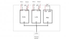
Can you make a drawing of your audio connections, ground connections, and earthing to the wall sockets?
No connection to mains safety earth, as I use USB for power input. But I did try a wire from the case of earthed equipment to the Retro case, with no difference.
Attachments
The outputs of your cartridge will be a balanced signal, which means it is possible to eliminate any interference if it is wired correctly. Ideally, both + and - singla s shoudl be exposed to the same interference, so that it can be cancelled out by the input section of the Retro.
If your balanced signals are running through standard shielded RCA lead, one of the signals it the shield, the other the center conductor. This arrangement will result in the shield signal receiving the bulk of the interference, and will result in noise, as the cancellation will be ineffective.
I recommend you ground the chassis of the turntable to the chassis of the pre-amp, as well as the mains earth to the chassis of the pre-amp. These should all tie to the same location in the pre-amp, close as possible to the mains input.
Whether you connect the audio signal ground to the chassis ground, as well as how you connect it will depend heavily on your particular configuration.
I am curious about your power source. It comes from the USB input?
There may also be a ground loop at play here, but it is hard to say, and the noise would not vary with placement, but it could be a secondary issue.
[NOTE: Just saw your internal pics above. Let me look at those for a bit.]
Brian,
thanks for taking a look at my problem!
Yes, unfortunately the tonearm cables are standard rca, leading the green and blue leads through each shield.
The turntable chassis is made out of dense foam, but I did try to ground the housing for the bearing and a motor case screw to the Retro chassis, with no luck. In addition another wire from the PE terminal of an outlet. Everything not better, nor worse.
For the power supply I use Jans/Linear Audio "Silent Switcher".
A USB keystone in Neutrik D type panel fitting is also isolating the 5V, gnd and shell from the case. For the 5V input I use a powerbank.
My other option is a AMB sigma22 I may also try, if swapping the turntable leads does not help.
I will get rid of the daisy chain power routing next thing, thanks for the hint.
Hi, after reading the whole thread I am still confused. In the schematic (post 55) the loading Resistors are 47K. But BrianL stated I would be effectively 94K. In my set there are still 47K resistors?Hi Brian, You are correct about the loading and the series caps. I have corrected that.
Cheers!
Russ
So how to set the load resistance for 47K (2 times 47K to 2 times 23K) or for my DV-20X2H I would like 1K (2 times 1K or 2 times 500 Ohm)? The same for the load capacitance. How to set it?
Regards
Branko
Hi, looked in for it but is unavailable.I use the Silent Switcher. As you know it has been unavailable for some time. I would think it should be back relatively soon.
My main point was what Voltage would be best? More to the 15V side or better for 12V?
thx Branko
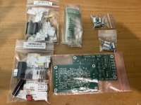
Hi, very interesting construction. I recently modified the board to use SMD, the resistors are mini melf, only the capacitors I left THT. I reckon they install from the opposite side. For those who would like to build it, the gerber files are attached.
Attachments

Just read the thread and i have been thinking about building a phono section. Not many people talking about how good it sounds MMMMMM.
But that wouldn't keep me from DIYing it. It's 50% about the journey!!!! So how dose the Hi Z sound and has any one compared it to
But that wouldn't keep me from DIYing it. It's 50% about the journey!!!! So how dose the Hi Z sound and has any one compared it to
Muffsy Phono Preamp https://www.tindie.com/products/skrodahl/muffsy-phono-preamp-kit/?pt=ac_prod_search
Last edited:

English please. Rules.
Repair gerber files. The copper layer was not included.Opravte soubory gerber. Měděná vrstva nebyla zahrnuta.
- Home
- More Vendors...
- Twisted Pear
- Retro - A fully symetrical phono stage with RIAA filter