salas said:I would smack the living daylights out of those luna park 6E2s!
Just wondering Is there a problem with it's Magic Eyes?
I've started to write up my findings on the various Yaqin models I've had here:
http://www.slickpepper.dyndns.org/valve-tube-amps
It's sparse at the moment, but I will add more.
Cheers,
Dan
http://www.slickpepper.dyndns.org/valve-tube-amps
It's sparse at the moment, but I will add more.
Cheers,
Dan
gingertube said:More complex mods:
Make up a little "matrix" board with a cascode transistor current source (or ring of two transistor current source) to replace the 30K/2W tail resistor in the driver stage and make the 2 anode loads the same - both 47K would be good.
Use separate cathode bias resistors and bypass caps for each 5881.
Cheers,
Ian [/B]
Hi Ian, can you explain more of the above? Is there any schematics? Thanks.
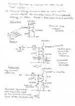
gingertube said:Hi,
Did'nt have time to do much but have scribbled some current sources on a piece of paper which would suit.
Cheers,
Ian
Hi Ian, thanks but I have a problem sourcing BC5465 from Farnell. In fact, there is any any match part no. Can you give other equivalent part for this?
salas said:See about substituting the stock gray coupling caps with something good, and you will get some expressionism in its sound. Also see for Blackgate FK instead of the stock cathode bias bypass output stage caps.
I'm waiting for the parts from Farnell now..
DanDini said:Whilst Salas is sorting the schematic, this picture may help you. Note that this is not the best way to lay these things out, but it's functional. Someone with more time and skill (or if I was doing it again) would do things differently.
An externally hosted image should be here but it was not working when we last tested it.
The circled parts are where modification has occured...
1. top and bottom left - some ground layout work (this may be trial and error - but the key thing is making all grounds go to chassis at the same point
2. middle left - one of the pairs of 500 Ohm 5 watt bias resistors removed
3. up and to the right is the resistor in the CRC filter. I used a 270 Ohm 20 watt which meant that I could leave the original 450v rated cap in place as it dropped sufficient volts to bring it into spec.
4. right of that is the 100uF 500V cap that makes up the CRC filter.
5. right of that is the other 500 Ohm bias resistor with it's friend removed
6. right of that is the pair of 0.33 Ohm 10 watt resistors that drop the heater voltage to 6.3v
7. The other circle at the bottom right shows where I replaced the original 0.22uF coupling caps with (cheap) polyprops. The fitted originals were only rated at 275v, although the schematic suggests 400v. They only see that kind of voltage with the valves out of circuit, but they may be worth changing anyway. Note that all the yellow cylindrical caps are replacements - I just haven't circled them all!
Hope this helps,
Dan
Hey Guys,
Just thought i'd show the guts of my amp with what looks like different components.
500ohm 6watt bias resistors x4
KMG 450v 22uf caps x4 & 100uf 100v x2 (change to blackgate caps recommended?)
220n k 275v caps (x6 change to polyprops 400v recommended?)
Yaoin 5881
Hi Guys,
Very interesting posts on the Yaoin5881a. This is my first posting but I have been emailing Dan for a while. Can you guys help me please? I have changed all the .22 caps for really nice MFD caps. The question is what will the extra capacitance do to the amp will it degrade the sound in anyway, like cutting down the highs etc. I have wima .22 caps that I can fit instead to bring it back to the correct uf value if necessary, but these MFD are beautiful quality and ill keep them if possible.
I have a chance to get a high voltage Siemens 3100 uf cap to replace the main 470uf electrolytic cap. How would that affect the sound? Can one get rid of the polarised electros and fit non-polarised metal film types instead?
Cheers, Roy
I got a Yaqin MC 5881 in for repair: a tube was blown in the input stage (noise like shotgun-noise became unbearable).
I suspected a damaged heater/kathode and inserted a new PCC88 just to test: it now worked and was silent.
And as wel, the amplifier got way too hot.
So I opened it and found here too in this continental country that the heater voltage was 7,2 volt AC on a 225 volt mains. This means the mains transformer is a 2x100 primairy that is sold in Europe. A bad shame. There is a remote danger even. long time heat, above 100 degrees; capacitors dry up and might blow away.
With the higher heater voltage the tubes will age very quickly (less than 1.000 hours?). The voltage dividers of the first stage do not work good anymore; the cathodes for the SRPP-top end and the phase splitter now run at 105 volt, meaning that the maximum heater/cathode voltage is violated: maximum is 80 volt for an 6N1/ECC88/6DJ8).
What to do?
We'll see how I progress.
A compliment though to the factory: I must say the amplifier is very well made.
albert
I suspected a damaged heater/kathode and inserted a new PCC88 just to test: it now worked and was silent.
And as wel, the amplifier got way too hot.
So I opened it and found here too in this continental country that the heater voltage was 7,2 volt AC on a 225 volt mains.
This means the mains transformer is a 2x100 primairy that is sold in Europe. A bad shame. There is a remote danger even. long time heat, above 100 degrees; capacitors dry up and might blow away. With the higher heater voltage the tubes will age very quickly (less than 1.000 hours?). The voltage dividers of the first stage do not work good anymore; the cathodes for the SRPP-top end and the phase splitter now run at 105 volt, meaning that the maximum heater/cathode voltage is violated: maximum is 80 volt for an 6N1/ECC88/6DJ8).
What to do?
- 1) Buy a new transformer (order to specs?) - which is costly.
2) use an autotrafo like mentioned in the thread before. 220v+30v should do. (225*220/250 = about 200). But I don't have one lying around.
3) disect the mains transformer. The windings for the heater are the ones on the outside. This is a complex job, peeling off the layers of isolation and finding the one that is 6,2 volt.
4) insert a resistor like said before in this thread --> I don't like this option. The transformer will remain just as hot.
5) use PCC88 tubes, they are pin-compatible and are made for 7.0 volt; the PCC189 is an alternative 7.4 volt) and can withstand 210 volt heater/cathode.
6) introduce an elevation for the heater current, of about 25 volt. This reduces the risk of breakdown. Use a 220k/22k plus 10 mu dividernetwork, taking out the ground loop of course of the led circuit.
We'll see how I progress.
A compliment though to the factory: I must say the amplifier is very well made.
albert
Hi,
I used the much advocated ECC88 as a replacement (pin-compatible) but I wondered how-come the tube was driven by such a high Vb (almost 380/400 volt).
Today I found out it is an ECC85 compatible tube!
Who agrees 6N1 = ECC85?
As far as I can see: ECC85 has a higher amplification factor (55 against 35).
triodeal
Hello, and happy new year from Domžale, Slovenija( we have a z letter with a roof turned around on it).
I found the debate here about MC5881 integrated tube amplifier more then very interesting..
I have OEM Yaqin MC-5881A(imported in Slovenija by brand name Tonewin, which is, i suppose, a name of the factory in China) and it performs really superb in my setup, after a few changes made on interconnnects and speaker wiring and a little tweak on internal wiring on tweeters of my speakers.
MC5881A is playing in my sistem extremely fast(i mean fast like transistor amp) and open in all aspects, with a wonderfull details and superb positioning of instruments, huge "out of the box stage, and not at in a split of a second, harsh..
This is my first tube amp(i m formerly a transistor "believer") and i purchase it after a whole day trial of Yaqin amps, that i organized as mod of one of high end DIY sloveninan forums in community centre in town where i live.
This one fitted on that trial on my setup, i brought there with other memebers of our sloveninan forum, like a glove in a spot.
Others Yaqins have not.
So i bougt it.
Considering i m a newbie in tube world(and just an audiophile, who doesent know a lot of electrononics , i will most probably ask you sometimes a stupid question, so please be patient with me..
Best regards, Jaro
Yaqin repairs
I finalised repairing the Yaqin.
I found that the transformer has 0,45 V per winding so I needed to take out two windings. In fact I just soldered a little wire after scraping off the isolation. It is now 6,3 volt AC.
Next I also did the following changes:
The result is very good, a clean sounding amplifier. No hum from the powersupply. No his.
Harmonics are very clearly heard in complex music (classical, strings).
Soundstage (depth) is easily perceived.
I play on an ESL57 from Quad. Not an easy speaker to use! But this amplifier shines. The CD I use is a Philips one with TDA1541A(*). A good reference.
albert
I finalised repairing the Yaqin.
3) dissect the mains transformer. The windings for the heater are the ones on the outside. This is a complex job, peeling off the layers of isolation and finding the one that is 6,3 volt.
I found that the transformer has 0,45 V per winding so I needed to take out two windings. In fact I just soldered a little wire after scraping off the isolation. It is now 6,3 volt AC.
Next I also did the following changes:
-
1 - add a 20 ohm resistor to the high voltage AC;
2 - add an RC stage in the high voltage supply: 4 muF plus 100 ohm 10 W. The capacitor is a Shizuki, a bit expensive but really worth the result. The rectifier has no overshoot. The Vb is now 405 V.
3 - change the 5k1 feeding the drivers to 12k. This gives the driver stage a healthier 345 V.
4 - I changed the output configuration: from ultralineair to triode connected. This is done by taking out the UL wire to pin 4 and connecting pins ¾ with a 47 ohm resistor. As well the cathode bias resistor must give -45 Vg @ 65 mA total (Tungsol specs). I opted for 600 ohm autobias, giving a measured Vg of -31 volts @ 25 mA each tube.
5 - I changed the feedback. The original circuit gives 41 dB amplification, good for an iPOD but useless in a normal installation with a CD. I replaced the 5k1/100pF with 1k2/500pF(mica). The amplification is now 28 dB. The volume works fine now.
6 - I also changed the feeding resistor for the drivers from 5k1 to 12k. This gives a Vb for the drivers of 345V. This is good.
7 - not really trivial: I bypassed the electrolytics on the SRPP with 220 nF. The MKP coupling caps are fine just as they are.
* I did not elevate the heater voltage. The drivers are at a DC level of 102L/105R volt, but the 6N1 or ECC85 can withstand that.
The result is very good, a clean sounding amplifier. No hum from the powersupply. No his.
Harmonics are very clearly heard in complex music (classical, strings).
Soundstage (depth) is easily perceived.
I play on an ESL57 from Quad. Not an easy speaker to use! But this amplifier shines. The CD I use is a Philips one with TDA1541A(*). A good reference.
albert
- Home
- Amplifiers
- Tubes / Valves
- Yaqin MC-5881A amplifier improvements