Hi milen007,
I'm away from home right now so can't label a photo, but hopefully this should guide you...
The recitifier is the small round black thing with 4 legs sitting above one of the two big capacitors. Two brown wires connect it to the transformer, and the other two legs connect to the first big brown cap. This is where the bypass should go - in parallel with the first big brown cap.
The grounds of the two big brown caps are connected, but there is a resistor between the two cap positive pins (CRC arrangement). The B+ feed is the wire leading from the positive side of the second big brown cap to the two valves. The bypass here should be positioned close to the two valves, in parallel with the second big brown cap.
The AC heater feed is the twisted pair of blue wires. I installed the bypass where the conductors are exposed and connected to the first valve (between the two conductors).
The input and output caps don't need to be supression type.
I can't comment on the effect of changing resistor values (I don't know what effect this would have).
I haven't changed the rectifier yet.
I disconnected the second big brown cap and installed a bigger & better cap in it's place (680uF). This made a big difference!
Good luck - let me know if any of this doesn't make sense.
edit for post above: about the resistor should be:
" how bout the 300k ohm substitute with 340k ohm?"
sharpi31, in my newbie words, is it bypass both the brown 150uf caps?
while the second cap that you change to 680uf is bypass in between two valves, instead of directly to the big cap as the 1st bypass.
whats the min voltage for all the caps including the 680uf?
blackgate nx 680uf 35v will do?
third bypass is to join the two exposed blue wire with capacitor near the LED? thx
i change the resistor to kimawe as suggested by L700 but use riken 10kohm to connect two pos leads from the two big caps with good result. sound smoother no more harsh
Milen007,
Yes, you should bypass both the brown caps. The bypass on the first cap should be located as close to the rectifier as possible. The bypass on the second should be close to the two valves. You are correct about the third bypass location.
From memory the B+ feed is 150V. I used a 400V rated cap - you'll need 200V minimum for this one. The three bypasses need to be 200V, 150V and 12.6V minimum, so just make them all 250V rated.
I can't remember which one it was, but either the input or output caps have 50V across them. Make both 100V rated as a minimum to be safe.
sharpi31 said:Milen007,
Yes, you should bypass both the brown caps. The bypass on the first cap should be located as close to the rectifier as possible. The bypass on the second should be close to the two valves. You are correct about the third bypass location.
From memory the B+ feed is 150V. I used a 400V rated cap - you'll need 200V minimum for this one. The three bypasses need to be 200V, 150V and 12.6V minimum, so just make them all 250V rated.
I can't remember which one it was, but either the input or output caps have 50V across them. Make both 100V rated as a minimum to be safe.
Thanks for the help. One more thing. Is the voltage ac or dc? I think dc right?
sharpi31 said:The heater feed is 12.6VAC. The rectifier ouputs 200VDC to the first brown cap. The series R drops this to 150VDC for the B+ feed.
heather feed of 12.6 VAC, is it safe just use normal 250vdc capacitor? just wondering as i read someone do "auricap tweek" that deal with ac suggested to get x2 suppression cap to be safe. 250vdc cap is 20 time the 12.5 VAC, is this safe enough?
") just precaution. thanks
just precaution. thanksmilen007 said:anyone has any idea whats the gain in db for this tube buffer 6j1? thx
milen007 said:anyone has any idea whats the gain in db for this tube buffer 6j1? thx
Cathode followers have a slight decrease in signal level voltage, but the reason cathode followers are used is that they increase the ability of the signal to drive heavier loads. If you have a SS amp with say 10K input impedance, and a source that has an output impedance of 1 megohm, and the signal voltage is 1V, the SS amp will see it as a 10mV signal. You get the effect as if the signal source is feeding a voltage divider resistor network of 1 megohm and 10K to ground, which will produce about 1% of the signal voltage. A cathode follower will reduce the signal's impedance to something that can drive 2/3V to 9/10V signal voltage into the SS amp.
A tube cathode follower can introduce some of that magic "tube flavor" aka 2nd harmonic about 45dB down into the music. The human ear likes a small amount of 2nd H, but really hates 3rd H. But be careful with the 2nd H, music with lots of instruments playing at the same time can make for "intermod", intermodulation distortion coming from the same mechanism that produced the -45dB 2nd H. Intermod makes for "muddy" sound, which is not pleasant.
wa2ise said:
Cathode followers have a slight decrease in signal level voltage, but the reason cathode followers are used is that they increase the ability of the signal to drive heavier loads. If you have a SS amp with say 10K input impedance, and a source that has an output impedance of 1 megohm, and the signal voltage is 1V, the SS amp will see it as a 10mV signal. You get the effect as if the signal source is feeding a voltage divider resistor network of 1 megohm and 10K to ground, which will produce about 1% of the signal voltage. A cathode follower will reduce the signal's impedance to something that can drive 2/3V to 9/10V signal voltage into the SS amp.
Hi wa2ise
thanks for the thorough explaination.
i have another question, i am using usb dac driving this cathode follower then follow by a preamp.
my preamp input impedance is 27k ohm.
what my usb dac see the input impedance of the next stage it drive?
1. whats the input impedance of this tube buffer?
500k ohm input impedance as being stated in the 1st page?
2. or as wa2ise state the cathode follower will reduce the signal's impedance from 2/3v to 9/10 which is roughly 30%. hence i assume my preamp with 27k input impedance + 30% = roughly 36k?
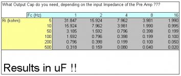
thanks for the help. as i am tuning the ouput cap in my usb dac. i have tried change from 10uf to 4.7 uf. its just so superb. hence i assume it will get better with correct capacitor value.
below i attached the output caps table. courtesy of Doede
DDDAC. how to use the table? whats "Fc" on the table? whats the best suggested value of my ouput cap for usb dac (which is not DDDAC)? presume that all output cap for DAC can follow this table? or is this application dependent?
regards, Erwin
Attachments
milen007 said:My answers inserted in not bold font - wa2ise
I have another question, i am using usb dac driving this cathode follower then follow by a preamp.
my preamp input impedance is 27k ohm.
what my usb dac see the input impedance of the next stage it drive?
1. whats the input impedance of this tube buffer?
500k ohm input impedance as being stated in the 1st page?
yes
2. or as wa2ise state the cathode follower will reduce the signal's impedance from 2/3v to 9/10 which is roughly 30%. hence i assume my preamp with 27k input impedance + 30% = roughly 36k?
The 9/10 to 2/3 numbers refer to the resulting audio voltage output, as compared to the input audio voltage. In your case, I don't know what exactly the cathode follower output impedance of the tube you're using, but it is likely 1k or so. Which will deliver something like 80% of the audio voltage amplitude to your preamp with the 27K input impedance.
thanks for the help. as i am tuning the ouput cap in my usb dac. i have tried change from 10uf to 4.7 uf. its just so superb. hence i assume it will get better with correct capacitor value.
It's not that critical. It only effects the bass end of the audio spectrum. If it sounds great, I'd leave what you now have in there.
below i attached the output caps table. courtesy of Doede
DDDAC. how to use the table? whats "Fc" on the table? whats the best suggested value of my output cap for usb dac (which is not DDDAC)? presume that all output cap for DAC can follow this table? or is this application dependent?
Fc is the point in the audio spectrum where the amplitude is 3 dB down from the maximum. Remember that 1 dB drop is not really noticeable by the human ear. Far away from this Fc point, the responses look like straight lines, but near Fc it transitions to a curve. Where the straight lines would have crossed is the Fc point. It's "poles and zeros" in Bode polts, which can give electrical engineering students in sophomore year fits...
regards, Erwin
wa2ise said:The 9/10 to 2/3 numbers refer to the resulting audio voltage output, as compared to the input audio voltage. In your case, I don't know what exactly the cathode follower output impedance of the tube you're using, but it is likely 1k or so. Which will deliver something like 80% of the audio voltage amplitude to your preamp with the 27K input impedance.
If thats the case, whats the ideal input impedance of my amp to get better drive from the buffer? 30k to 50k?
will this added stage of tube buffer help with the impedance matching of each stages of the whole systems? or better of without them?
i am also wondering as athos56, whats the purpose of input caps of this cathode followers? as this is not likely as dc filtering since some also do not has input caps as athos56 claimed. thx in adv
coresta said:A lot lesser than 30k ! for a pentode Cf , the average source impedance is given by the formula : 1 / S (slope) . The 6AK5 gives an average value of 5mA/V so : 200ohms
Hi Coresta
mind elaborate? less than 30k input impedance? 6ak5 current draw is 5mA/V?
no... a CF buffer is an gain amp where input impedance is high , very high , an unity gain (0,95 average) , and a low output impedance . At a certain working point of drawn current, given in data sheets , the slope reaches a certain value :this point is the S of the 1/S formula . The higher the slope , the lesser the Z ! So it'll be able to load any any preamp from 10k without any problem
- Status
- This old topic is closed. If you want to reopen this topic, contact a moderator using the "Report Post" button.
- Home
- Amplifiers
- Tubes / Valves
- Tube Buffer 6J1 / 5654 (6AK5)