Just wondering if there is such design or may be it's already apply in some commercial tube DAC / CD plyaer.
I have bought some ECC83/12AX7 (NOS). But don't feel like buying a big transformer to build a pre-amp. What i was thinking is.. can i used some kind of power supply that samilar to CTV. Rectifier the AC direct from home socket. Throgh a switching circuit get 6.3V & 250V from the secondary of the switching transformer. Imagine that by doing so. It shall min the size of the conventional 50 Hz tranformer. Reservour cap also can be reduce in size. Will it works? All inputs are welcome.
I have bought some ECC83/12AX7 (NOS). But don't feel like buying a big transformer to build a pre-amp. What i was thinking is.. can i used some kind of power supply that samilar to CTV. Rectifier the AC direct from home socket. Throgh a switching circuit get 6.3V & 250V from the secondary of the switching transformer. Imagine that by doing so. It shall min the size of the conventional 50 Hz tranformer. Reservour cap also can be reduce in size. Will it works? All inputs are welcome.
This was discussed in another thread, you should always have some sort of isolation, never use the mains power directly and rectify it for the HV.
Here's a great inexpensive power transformer for a pre-amp, which I've used already. Very economical (under $15)
http://www.alliedelec.com/Search/SearchResults.asp?N=0&Ntk=Primary&Ntt=6K1VF&sid=45B6A18043A0E17F
Another way that works well is two filament transformers back-to-back.
Here's something along these lines, for example:
http://www.lh-electric.4t.com/projects/budget_ps.htm
THanks, SY. But, I am not talking about rectify direct from 230 AC supply & used it as HT. What i am saying is.. build a something like PSU found in PC. Isolate the mains, make the swtching trans generate 6.3v for heater & 200v - 250v HT..SY said:Insanely dangerous for the home constructor without the ability to do proper double insulation. Don't even think about it.
Just as long as you have the 230vac isolated because if you didn't and something went wrong 220 make an arc that look's like a fire it has no problem vaporizing 1\4 inch bolts I have seen it unfortunatly. I you ever come in contact with this or are doing a initial power up and adjustment and are close to the amp when this happens make no mistake you will be severly burned.
And If your eye's are close to the amp you will be blind and could possibly lose your eye's all together.
Rectified or not Isolate it THE DANGER is very real !!!!!
Just dont want to see anyone get hurt.
Nick
And If your eye's are close to the amp you will be blind and could possibly lose your eye's all together.
Rectified or not Isolate it THE DANGER is very real !!!!!
Just dont want to see anyone get hurt.
Nick
Gotcha. Switching supplies in preamps have a long and honorable history. A buck/boost converter/reg for 200-300V is very doable. First commercial preamp I know that did this was the late 1970s Berning TF-10, followed by the late 1980s TF-12. The schematic might be of historic interest to you.
http://www.davidberning.com/tf-10.htm
http://www.davidberning.com/tf-12.htm
http://www.davidberning.com/tf-10.htm
http://www.davidberning.com/tf-12.htm
Here's an article that describes exactly what you want -
"Regulated High-Voltage Supply For Valve Amplifiers
How to modify a surplus PC power supply to produce a 700V or 400V high-voltage rail"
You'll find it at:
http://www.siliconchip.com.au/cms/A_102096/article.html
Although it will cost $5 - still think of all the money saved on PTs.
I just downloaded it myself & am reading through.
Extract from article "The circuit is capable of excellent performance. It maintains full regulation at up to 125W, with ripple at 2V peak-to-peak, or 0.3% at full power. This is quite acceptable, as most of the ripple is at twice the switching frequency (60kHz) and so is inaudible.
The 100Hz hum component is only 0.08%, which shows the excellent regulation of the TL494, since the rectified mains source contains 13% of 100Hz ripple at full power. Over-current protection is retained, with a LED added to indicate when it is active. "
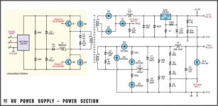
I believe it is safe - Would be interested in discussing it here. Here's the final schematic.
"Regulated High-Voltage Supply For Valve Amplifiers
How to modify a surplus PC power supply to produce a 700V or 400V high-voltage rail"
You'll find it at:
http://www.siliconchip.com.au/cms/A_102096/article.html
Although it will cost $5 - still think of all the money saved on PTs.
I just downloaded it myself & am reading through.
Extract from article "The circuit is capable of excellent performance. It maintains full regulation at up to 125W, with ripple at 2V peak-to-peak, or 0.3% at full power. This is quite acceptable, as most of the ripple is at twice the switching frequency (60kHz) and so is inaudible.
The 100Hz hum component is only 0.08%, which shows the excellent regulation of the TL494, since the rectified mains source contains 13% of 100Hz ripple at full power. Over-current protection is retained, with a LED added to indicate when it is active. "
I believe it is safe - Would be interested in discussing it here. Here's the final schematic.
Attachments
A switching supply is definatly not worth it for a pre-amp since the transformers arn't big at all. However they could be ok for an power amplifier because when power dissapation gets large so do the magnetics.
I tend to agree with this statement. The power transformer for a preamp is relatively small and cheap. The signal levels in a preamp are far lower than those in a power amp. The peak currents in a SMPS are far higher than those in a conventional power supply so it is harder to isolate the supply currents from the signal currents. An SMPS still has some 50/100 (60/120) Hz ripple as well as a lot of high frequency content. If this gets into the signal the amp just doesn't sound right. Do you want to chase hum, or hum and HF noise.
I have experimented with SMPS's for audio power amps with limited success. I have designed and built SMPS's for projects at work. I am about to travel down that road once again. This time it will be a completely digital design. Check this out:
http://www.microchip.com/stellent/idcplg?IdcService=SS_GET_PAGE&nodeId=2524¶m=en027097
The supply voltage can be modulated by the audio signal and a CCS function could be easilly implemented. SE parafeed without the choke.
A word of caution (don't ask me how I know this), in addition to the obvious electrical safety issues (use an isolation transformer for testing). Whenever working on any circuit connected directly to the line voltage, beware of the possibility that the circuit can explode violently with no warning. Even with a fuse at the input, there is enough energy stored in the capacitors to instantly varorize a mosfet. The resulting shrapnel is extremely hot. I place a thick piece of Lexan over the circuit before power up and keep a fire extinguisher nearby!
You must be prepared to sacrifice a few mosfets to the fire gods.

I am also working on a supply right along these lines. Completely from scratch, it will provide 450V@600mA, -150V@150mA, and 6.3V@10A. (356W total output) I am not an audio tube person (my friend is doing that part), but I have significant experience in solid state/high voltage design.
A few characteristics/things worth mentioning:
--PFC boost front end to 400VDC non-isolated, so there are only small energy storage capacitors for a light startup current. There is also an NTC right on the AC input, which is always a good idea to avoid flickering lights on turn-on.
--It is of push-pull design, so there is little ripple on the secondary at moderate to high duty-cycles. This type of design, however, necessitates high voltage MOSFETs (800V + transients + safety margin), so it will use 1000V or 1200V FETs. Prices for these are actually quite reasonable (less than $4-6 each).
--Because of the selection of ferrite cores that I have, I am building the three supplies on two or three separate cores. This will also also independent regulation of the supplies, which I like since I am not sure (he doesn't know yet) what the tubes will need.
--Fully optoisolated secondary feedback
I will post more information after I get the PCB designed, ordered, and constructed.
I you have any questions, feel free to ask.
JasonLee, it would not be that hard to do what you require. There may be a COTS switching transformer to make your design easier, though I haven't looked around yet. You should be able to build a simple forward converter. I believe that the biggest knowledge barrier to these types of supplies are the magnetics design. Look around ti.com for applications notes on this for a start. They have many good articles on this subject.
jkeny said:Here's an article that describes exactly what you want -
"Regulated High-Voltage Supply For Valve Amplifiers
How to modify a surplus PC power supply to produce a 700V or 400V high-voltage rail"
You'll find it at:
http://www.siliconchip.com.au/cms/A_102096/article.html
Here is one builders experience with this kit:
12AX7 Tube Preamp Kit
He reports very good results and it measures well.
EDIT: My mistake, the 12AX7 uses a different uses a different switch mode supply. Sorry.
- Status
- This old topic is closed. If you want to reopen this topic, contact a moderator using the "Report Post" button.
- Home
- Amplifiers
- Tubes / Valves
- Switching power supply for tube-pre