I used TIP50 (or any other similar HV bipolar or FET) and the 317 because they're cheap and easy, and it performs well. I've also never lost one in actual use, just in doing stupid things poking around with probes. I do these things in order to show my fallibility.
There are a lot of other good regulator solutions. I've never used the TL783, but it would probably work OK if you could arrange it to survive turn on and turn off. The sweet thing here is that the screens are high level and common mode. Makes life easy.
There are a lot of other good regulator solutions. I've never used the TL783, but it would probably work OK if you could arrange it to survive turn on and turn off. The sweet thing here is that the screens are high level and common mode. Makes life easy.
yes, actually, I read it right before I posted,
so you are seggesting that I use something closer to what is in documentation?
http://www.national.com/ms/LB/LB-47.pdf#page=1
I liked yours because it seemed to make more sense to me as I have a limited knowladge of semiconductors. but the way I see it, your design does not have the error correcting feedback created by the diodes, am I right? also, adding more caps, should I just put two caps on either side of the regulator circuit? I have (at least) thirty 680uf 200vac capacitors (the fruits of disecting 20+ computer power supplies) I could put two of those in series on each side of the regulator.
Would all the resistor values stay the same? I am still sketchy on what some of them do, but I really want to learn how to harness the power of Linear regulators.
The orignal design uses a 5W pot where yours does not say, is this because of the resistor network that you have implimented?
Thank you so much, you've already been extreemly helpful
Actually, the diodes aren't for feedback, they're for protection. Nominally, anyway; I've still popped lots of devices during testing and probing around, though I have never lost one in normal use. The feedback is from the resistor going from the sense terminal to ground and the resistor going from the output terminal to the sense terminal.
Yes, you can use something like figure 1. The caps you have are probably way too large for this- you want values like 10-50uF. You can also get by without the Darlington; a reasonable-hfe pass device like TIP50 or even the NSD134 (no longer made) will do fine for low current service. You could even use a MOS device like IRF820. I'll sketch up something suitable later tonight.
The other alternative is to use a simple two transistor regulator. For a phono stage, the load is constant (class A), so you don't need fabulous dynamic regulation, just a good, steady, low-noise rail. See my article on the Heretical preamp for an implementation that will work fine for you.
Uhhh...yeah.... that's right.
Anyway, here you are. I breadboarded it to confirm operation. The output voltage was actually a bit low, so if the 300V were critical. you could tack a trimming resistor across the 200R. In my case, a 10k trim would have nailed the voltage.
Now this is quiet enough for a lot of phono stages where the power supply rejection is decent, but if you're doing something like a cascode that has essentially no PSR, you'll need a fancier supply than this.
If you've got plenty of B+ to burn, you could even make my simpler screen supply version of the Maida good enough by adding three or four cascaded RC sections. After all, your phono stage IS class A.
Attachments
")
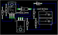
Alright, Thanks alot, I spent an hour putting that into eagle, and routing a plan to be made on a proto-board (I'm too cheap to have PCBs printed) What do you think of the outline? feel free to tear it to pieces, as I am not an expierenced board builder at all....
Attachments
ray_moth said:SY, is this kind of regulator stable if the output is shunted with a large smoothing cap (say, 220uF) to reduce PS noise?
Yes, it is. I might add one more diode around the reg and pass transistor for turn-off protection.
Alex, I'm the single worst person to ask about PCBs. But you do want all the grounds to connect at one point, which they do not seem to be here. You also want the 200R to connect as close to the 317 output as you can.
edit: And leave room for a small heatsink for the pass transistor.
I know, I just started building PCBS last week, (this is number 2 for this project), The other being a low Voltage regulator for the heaters, The three grounds are connected on a single trace, but yeah, I really should move them closer together, This is merley a guide to what will actually be put on a protoboard, so Traces will be wires, and it will probably be 2 layered before all is said and done. I can move the 200ohm R closer without much issue.
I'll order the parts by monday
-Moose
I'll order the parts by monday
-Moose
Oh, no, you certainly want to place your filtering before the regulator. "Raw" in this case means "unregulated supply." The nice thing is that the raw supply need not be anything special; the regulator will knock out drift and ripple very effectively. As always, grounding and wiring are everything.
- Status
- This old topic is closed. If you want to reopen this topic, contact a moderator using the "Report Post" button.
- Home
- Amplifiers
- Tubes / Valves
- Red Light District Amp Screen Reg