A little while ago, just for fun, I trained some neural networks (theoretically universal function approximators) on tube curves, then extracted the parameters out of the neural net as a long function, and used that in ltspice to model a few tubes. After considerable effort, I'm back at using curvecaptor to model tubes. Good enough for rough planning, and I wouldn't trust any better models anyway. At the end of the day it's still the real tube in a real circuit that finalizes the design, for me anyway.
A little while ago, just for fun, I trained some neural networks (theoretically universal function approximators) on tube curves, then extracted the parameters out of the neural net as a long function, and used that in ltspice to model a few tubes. After considerable effort, I'm back at using curvecaptor to model tubes. Good enough for rough planning, and I wouldn't trust any better models anyway. At the end of the day it's still the real tube in a real circuit that finalizes the design, for me anyway.
Hello,
For rough planning or what if thinking SPICE is the perfect tool.
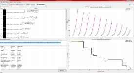
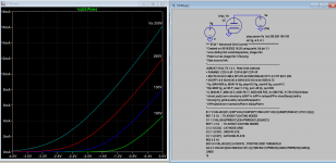
This circuit may never be built but it helped me understand what I know. I have been thinking of a new RIAA pre amplifier that uses a cascode input stage. I picked a 6DJ8 out of the sky because there are good models out there and it started life as a RF cascode tube. I found that the top tube really does shield the bottom grid from Miller capacitance and the bandwidth is huge, this is not news. Seeing the output helps the understanding. Also noted the gain can be huge, like 90 plus, also not news. What is news to me is that a resistor can be put in series with the bottom triode bypass capacitor and the circuit gain can be adjusted to any value over a wide range suitable for moving coil to moving magnet.
This may never be built in the real world but it does works in SIM.
If it is built the computer will go back to work testing the results.
DT
All just for fun!
I haven't used Eureqa for tubes, i have used it for light dependent resistors --
The program allows you to use several operators, + - x /, log, exp plus trig. You can also select which type of error to optimize. It will give you a very good fit for one series. You can separate the data sets and get good fits for multiple series.
The hyper expensive version of Multisim (Pro Professional) allows curve tracing, but you can do it by exporting the data from the grapher to Excel and creating a series of XY plots. Use a "piecewise linear source" for the grid voltages, and the function generator in triangle mode generator for the plate. No reason you couldn't do this in LTSpice.
This is what it looks like:
An externally hosted image should be here but it was not working when we last tested it.
multisim errors
Hi there
I have troubles with simulation models in multisim.
maybe someone can help what it means these errors, I am not yet as good
with making models.
I have include the models for use it have a lot in them, also the difficult ecc99, 6n6p etc, and the power penthodes and triodes.
I made a snip from screen with the errors, it is in multisim tryout.
Attachments

Eureqa
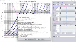
If been trying out the Eureqa program for modeling tube curves. Once you get the hang of the program and have the right settings the outcome is quite usable.
Not all solutions found work well in spice, especially the "big size" formulas tend to give problems (I used MicroCap).
Best results so far were obtained when using the "Akaike" Fitnes metric.
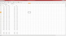
I used Excel to obtain the points needed for Eureqa.
Attached are the Excel file and some pictures, I used an 300b curve.
If been trying out the Eureqa program for modeling tube curves. Once you get the hang of the program and have the right settings the outcome is quite usable.
Not all solutions found work well in spice, especially the "big size" formulas tend to give problems (I used MicroCap).
Best results so far were obtained when using the "Akaike" Fitnes metric.
I used Excel to obtain the points needed for Eureqa.
Attached are the Excel file and some pictures, I used an 300b curve.
Attachments

Last edited:
Hi All,Here are some spice models for various tubes I have recently added to my library, some are probably better than others. I used curve captor to create the models and then subsequently added the most important interelectrode capacitances.
.subckt 71a A G K
- 71a Model
- Traced by Kevin Kennedy 4.14.07 using Curve Captor
Bp A K I=(0.01920353249m)uramp(V(A,K)*ln(1.0+(-0.5900909656)+exp((4.378369184)+(4.378369184)((3.075663641)+(-0.4532604061m)V(G,K))V(G,K)/sqrt((-1.305099924e-006)**2+(V(A,K)-(4.436434761))**2)))/(4.378369184))(1.723372081)
*Capacitances
CGK G K 3.2p
CGA G A 7.5p
CAK A K 2.9p
.ends 71a
.subckt 6021 A G K
- 6021 Model
- Curve Captor model
Bp A K I=(0.007237439803e-3)uramp(V(A,K)*ln(1.0+(0.02398363722)+exp((2.884836093)+(2.884836093)((42.12840035)+(-332.3837771e-3)V(G,K))V(G,K)/sqrt((3.013312381e-006)**2+(V(A,K)-(-10.83109222))**2)))/(2.884836093))(1.626318011)
*Capacitances
CGK G K 0.7p
CGA G A 1.5p
CAK A K 0.28p
.ends 6021
* 5744 Model
*Traced by Kevin Kennedy 11.21.06 using Curve Captor
.subckt 5744 A G K
Bp A K I=((0.004400033102m)+(0.0005981672849m)*V(G,K))*uramp((53.41879747)*V(G,K)+V(A,K)+(-17.32853498))**1.5 * V(A,K)/(V(A,K)+(-19.03861576))
*Capacitances
CGK G K 3.4p
CGA G A 0.95p
CAK A K 3.0p
.ends 5744
* D3A Triode connected model
*Traced by Kevin Kennedy 12.15.06 using Curve Captor
.subckt D3AT A G K
Bp A K I=(0.01421213952m)uramp(V(A,K)*ln(1.0+(-0.3656855867)+exp((0.05161803446)+(0.05161803446)((1347.92881)+(-149831.3787m)V(G,K))V(G,K)/sqrt((22.06449306)**2+(V(A,K)-(-9.250221191))**2)))/(0.05161803446))(1.193961005)
*Capacitances
CGK G K 7.3P
CGA G A 2.7P
CAK A K 3.1P
.ends D3AT
These should be compatible with any spice program that supports 3F4 models and were created specifically for LTspice.
You can copy and paste these directly into your own tube library.
Most, but not all are Koren 8 parameter models, see if you can spot the one that isn't..
These models are provided without warranty and for personal use only.

Does anyone have an alternative LTspice model for 5744 tube posted above?
I'm using it to simulate a guitar amp. For low signals (below clipping) all works well. For large input signals, the simulations never complete as the time steps get very small and the output signal can get very large (i.e. mega volts instead of hundreds of volts). For the same circuit i've used other tube models i.e. 12ax7 and 8532w model and it works perfectly in my circuit, but when I use the 5744 model listed above it never converges, hence the request for an alternative model.
Kind Regards,
Ted
Convergence issue maybe resolved with the following options (example) and use Alternate resolver (in Spice control panel):
.option noopiter
.options GminSteps=0
.options SrcSteps=1000
Here is Paint Tool Tung-Sol model to try:
.option noopiter
.options GminSteps=0
.options SrcSteps=1000
Here is Paint Tool Tung-Sol model to try:
Code:
**** 5744 ** Advanced Grid Current **********************************
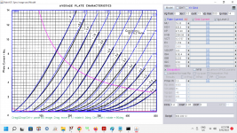
* Created on 05/16/2022 18:20 using paint_kit.jar 3.1
* www.dmitrynizh.com/tubeparams_image.htm
* Plate Curves image file: 5744.png
* Data source link:
*----------------------------------------------------------------------------------
.SUBCKT 5744_TS 1 2 3 ; Plate Grid Cathode
+ PARAMS: CCG=3.4P CGP=0.95P CCP=3P
+ MU=79.35 KG1=488.4 KP=473.48 KVB=2094.96 VCT=-0.1757 EX=1.259
+ VGOFF=-0.6 IGA=8.3E-4 IGB=0.033 IGC=4.64 IGEX=2.72
* Vp_MAX=500 Ip_MAX=14 Vg_step=0.5 Vg_start=0 Vg_count=13
* Rp=4000 Vg_ac=55 P_max=1.3 Vg_qui=-48 Vp_qui=300
* X_MIN=65 Y_MIN=32 X_SIZE=781 Y_SIZE=550 FSZ_X=1296 FSZ_Y=736 XYGrid=false
* showLoadLine=n showIp=y isDHT=n isPP=n isAsymPP=n showDissipLimit=y
* showIg1=y gridLevel2=y isInputSnapped=n
* XYProjections=n harmonicPlot=n dissipPlot=n
*----------------------------------------------------------------------------------
E1 7 0 VALUE={V(1,3)/KP*LOG(1+EXP(KP*(1/MU+(VCT+V(2,3))/SQRT(KVB+V(1,3)*V(1,3)))))}
RE1 7 0 1G ; TO AVOID FLOATING NODES
G1 1 3 VALUE={(PWR(V(7),EX)+PWRS(V(7),EX))/KG1}
RCP 1 3 1G ; TO AVOID FLOATING NODES
C1 2 3 {CCG} ; CATHODE-GRID
C2 2 1 {CGP} ; GRID=PLATE
C3 1 3 {CCP} ; CATHODE-PLATE
RE2 2 0 1G
EGC 8 0 VALUE={V(2,3)-VGOFF} ; POSITIVE GRID THRESHOLD
GG 2 3 VALUE={(IGA+IGB/(IGC+V(1,3)))*(MU/KG1)*(PWR(V(8),IGEX)+PWRS(V(8),IGEX))}
.ENDS
*$Attachments
Last edited:
Thanks kindly for your time and for generating the model. It works perfectly. I can overdrive the preamp now without any issues.Convergence issue maybe resolved with the following options (example) and use Alternate resolver (in Spice control panel):
.option noopiter
.options GminSteps=0
.options SrcSteps=1000
Here is Paint Tool Tung-Sol model to try:
Code:**** 5744 ** Advanced Grid Current ********************************** * Created on 05/16/2022 18:20 using paint_kit.jar 3.1 * www.dmitrynizh.com/tubeparams_image.htm * Plate Curves image file: 5744.png * Data source link: *---------------------------------------------------------------------------------- .SUBCKT 5744_TS 1 2 3 ; Plate Grid Cathode + PARAMS: CCG=3.4P CGP=0.95P CCP=3P + MU=79.35 KG1=488.4 KP=473.48 KVB=2094.96 VCT=-0.1757 EX=1.259 + VGOFF=-0.6 IGA=8.3E-4 IGB=0.033 IGC=4.64 IGEX=2.72 * Vp_MAX=500 Ip_MAX=14 Vg_step=0.5 Vg_start=0 Vg_count=13 * Rp=4000 Vg_ac=55 P_max=1.3 Vg_qui=-48 Vp_qui=300 * X_MIN=65 Y_MIN=32 X_SIZE=781 Y_SIZE=550 FSZ_X=1296 FSZ_Y=736 XYGrid=false * showLoadLine=n showIp=y isDHT=n isPP=n isAsymPP=n showDissipLimit=y * showIg1=y gridLevel2=y isInputSnapped=n * XYProjections=n harmonicPlot=n dissipPlot=n *---------------------------------------------------------------------------------- E1 7 0 VALUE={V(1,3)/KP*LOG(1+EXP(KP*(1/MU+(VCT+V(2,3))/SQRT(KVB+V(1,3)*V(1,3)))))} RE1 7 0 1G ; TO AVOID FLOATING NODES G1 1 3 VALUE={(PWR(V(7),EX)+PWRS(V(7),EX))/KG1} RCP 1 3 1G ; TO AVOID FLOATING NODES C1 2 3 {CCG} ; CATHODE-GRID C2 2 1 {CGP} ; GRID=PLATE C3 1 3 {CCP} ; CATHODE-PLATE RE2 2 0 1G EGC 8 0 VALUE={V(2,3)-VGOFF} ; POSITIVE GRID THRESHOLD GG 2 3 VALUE={(IGA+IGB/(IGC+V(1,3)))*(MU/KG1)*(PWR(V(8),IGEX)+PWRS(V(8),IGEX))} .ENDS *$
In regards to your screenshots, ive noticed that all your sliders are in the center.
Did the program auto-generate the parameters or did you manually slide them until you got close enough?
Once again, thankyou.
Hi All,
I've designed a preamp with about eight 12ax7s. I would like to test multiple 12ax7 models and even other try others such as the 12at7, 5744...
Is it possible to create a single global variable that I can change in a single place and have that model apply to all preamp tubes in the circuit?
For example something like TubeModel={NH12AX7}
Kind Regards,
Ted
This is how I do it:
Make a copy of the 12ax7 model file open and change ".Subckt 12ax7" to ".Subckt 1", another 12ax7 model as ".Subckt 2" and so on.
Name all the tubes as {TubeModel} instead of "nh12ax7"
.param TubeModel=1 will point this model 1.
.param TubeModel=2 will point another model 2.
Make a copy of the 12ax7 model file open and change ".Subckt 12ax7" to ".Subckt 1", another 12ax7 model as ".Subckt 2" and so on.
Name all the tubes as {TubeModel} instead of "nh12ax7"
.param TubeModel=1 will point this model 1.
.param TubeModel=2 will point another model 2.
Last edited:
- Home
- Amplifiers
- Tubes / Valves
- Tube spice models