Some exchages with Tubelab have inspired me to build an SE amp similar to his Simple SE design, but using a 6AH6 pentode in triode mode at the input and a 1625 output tube (both extremely cheap and plentiful). I'm using the budget Edcor 5K single ended transformers at the outputs. The unit will be powered with an SMPS of my own design, providing power for both B+ and filaments. the whole shooting match will go in a 6" cube with the tubes poking out on top and the output iron and power supply inside. Finish will be black crackle, with a blue LED pilot light to complement the plate wires. Attached is a picture of the top deck. Next step is to power up the amp with a couple of bench supplies to look for screw-ups and check bias points. After that it's wring out the power supply (built and putting out voltage, but still needing a real going-over and EMI scan), integrate supply and amp, and throw it in the box. Schematic for the amp will follow when I'm sure it's all working.
Hi
Going back to the start of this thread you mentioned you were designing your own SMPS. How did that work out? I have often thought of going along the same path myself. I have designed a few SMPS myself, winding the transformers is a pain as is removing noise from the output. Although this is a forum for vacuum tubes I would be happy to see a thread on a SMPS specifically designed for tube amplifiers. I believe it would be best to use off the shelf SMPS transformers. I did think of using an approved transformer in a supply, mains to 24VDC and then using a buck converter for the 6.3VDC and a two boost converters <= 4 to 1 step up ratio (x2) for HV. So 24V to 96VDC then to HV required, LT spice suggests this can be quite efficient.
Ken K
You scheme sounds unnecessarily complex. I am using a current-fed-push-pull scheme with outputs for +400, +200, 12V filament, and an unused output for +/- bias. Regulation is provided by the 24V SMPS that drives the input, and should be far superior to the usual line frequency transformer/rectifier setup.
Hi Wrenchone, Thanks for the reply. I agree the push-pull topology is much simpler.
The idea of using a 24V supply has a lot of merit.
Do you wind your own transformers? Is the SMPS in a shielded box?
I may even run up a PP PCB for testing as I have a good selection of ferrite cores. I have found PP tends be easier to tame re RFI than flyback.
I find the actual transformer winding a bit of a pain, my idea was to use "off the shelf inductors" and control the entire thing using a PIC micro. Leakage inductance is no problem with the proposed method, a slight drawback is a common gnd for the +6.3V, HT and bias. Using the PIC removes a lot of hardware.
Ken K
I wind my own transformers - not a really big deal, as I have been designing SMPS as my job for 40 years. A lot of the IP in my SMPS designs is bound up in the transformer, especially with measures to reduce EMI. I need to perform a similar investigation for the push-pull DC-DC transformer that I did for my flyback design 13 years ago. It took several iterations of transformer design back then before I came up with a reasonably quiet power supply.

A Productive Afternoon...
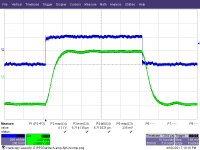
OK, I invested in some low value, HV ceramic caps to have more options for inner loop compensation for this amplifier. This sped up the inner loop, and gave me more options for compensating the amp in closed loop mode.
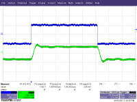
First up is the square wave response for open global loop with inner loop compensation of 5pF + 22k. The next pic shows square wave response for closed loop with no global loop compensation.
OK, I invested in some low value, HV ceramic caps to have more options for inner loop compensation for this amplifier. This sped up the inner loop, and gave me more options for compensating the amp in closed loop mode.
First up is the square wave response for open global loop with inner loop compensation of 5pF + 22k. The next pic shows square wave response for closed loop with no global loop compensation.
Attachments
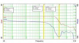
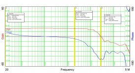
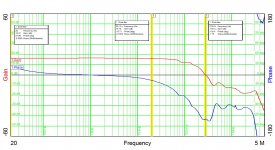
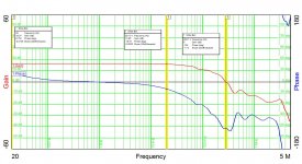
Next up, we have a series of closed loop G-P plots for compensation values of 0, 1nF, 1.5 nF, and 2.2nF.
The higher compensation values show a little (I mean a little) bit of sag at 20kHz in exchange for more phase margin at gain crossover. A stable amp is loads more important than a perfectly flat amp...
The higher compensation values show a little (I mean a little) bit of sag at 20kHz in exchange for more phase margin at gain crossover. A stable amp is loads more important than a perfectly flat amp...
Attachments
Last edited:
JHStewart -
The gain-phase data was taken using a Venable 6305 analyzer. It only goes up to 5 MHz, but that's good enough for things like tube amps and switching power supplies (the latter is its real purpose in life).
I have some options for distortion measurement that need to be polished up - I have an HP8903 analyzer, one of the old Sound Technology analyzers (probably needs a recap), and a Millett interface box plus an E-Mu USB interface. When I have time, I'll get one of the options on the case. The HP8903 is probably the quickest option, and its precision is sufficient for something like this tube amp.
No sim data - I haven't been very proactive on investigating options for tube circuit simulation, though I do it all the time for my solid state projects.
- Status
- This old topic is closed. If you want to reopen this topic, contact a moderator using the "Report Post" button.
- Home
- Amplifiers
- Tubes / Valves
- "Shrine" SE Amp using 6AH6 and 1625