Member
Joined 2009
Paid Member
This looks interesting.
This is a greedy tube, it uses plenty of heater current and the high grid voltage means burning power in the cathode 'resistor' too. But it will provide lots of drive. I have a SET based on the 6AS7 (two 6S19P in a bottle) which sounds better than a 'cheap' amp should have any claim to do. In fact I think I'll be dusting it off soon given the drop in ambient temperature at this time of the year. These tubes look great, the dual-split plate structure allows a fair bit of glow to be visible from the heater - all the working bits are fully visible, very satisfying.
my CELLINI triode amp
Last edited:
Maybe it will upset someone:
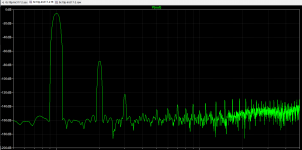
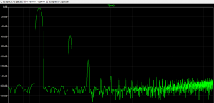
Harmonic distortion spectrum in vacuum tubes (THD tubes)
E. KARPOV, Odessa,
Ukraine
?????? ????? 11 ????? 2003 ???.
http://www.next-tube.com/articles/spectr/spectrRU.pdf
The possibility of using the 6S19P tube is very controversial. This tube has a low third harmonic level but the longest harmonic tail.
(Возможность использования лампы 6С19П весьма спорная. У этой лампы маленький уровень третьей гармоники, но самый длинный гармониковый хвост.)
Last edited:
In the USSR, there were levels of product acceptance quality (approximately):
1 the military is the best
2. For industry, industry appliances - the worst of the best
3. For home appliances, the worst
4. For repair parts for home appliances. worst of the worst
Acceptance category can give different measurement results
1 the military is the best
2. For industry, industry appliances - the worst of the best
3. For home appliances, the worst
4. For repair parts for home appliances. worst of the worst
Acceptance category can give different measurement results
Maybe it will upset someone:
Harmonic distortion spectrum in vacuum tubes (THD tubes)
E. KARPOV, Odessa,
Ukraine
?????? ????? 11 ????? 2003 ???.
http://www.next-tube.com/articles/spectr/spectrRU.pdf
The possibility of using the 6S19P tube is very controversial. This tube has a low third harmonic level but the longest harmonic tail.
(Возможность использования лампы 6С19П весьма спорная. У этой лампы маленький уровень третьей гармоники, но самый длинный гармониковый хвост.)
I've seen this article before.
Its not so useful to compare valves with very different Ra, using a static anode load.
Given the 6s19 has a very low Ra, I'm confident the THD 'tail' will be markedly different, with a 2k5 load!
Even then the load is 5×Ra, and the user could go 2k.
I have a quad of 6s19 laying about, that I should try out, but I'm fairly sure the valves poor performance in this article, has much to do with the bad load (10×ra)
Last edited:
Hi!
Anyone thinking in this little Russian tube has a clever little solution. I build it myself - once.")
(Sorry, with the site's props - inserting a link - I can't find a solution.
I hope I’m not doing this inconvenience.)
Monoblöcke mit der russischen Triode 6S19 (6C19P) in Gegentaktschaltung, von Thomas_Moppert
Anyone thinking in this little Russian tube has a clever little solution. I build it myself - once.
(Sorry, with the site's props - inserting a link - I can't find a solution.
I hope I’m not doing this inconvenience.)
Monoblöcke mit der russischen Triode 6S19 (6C19P) in Gegentaktschaltung, von Thomas_Moppert
I've seen this article before.
Its not so useful to compare valves with very different Ra, using a static anode load.
Given the 6s19 has a very low Ra, I'm confident the THD 'tail' will be markedly different, with a 2k5 load!
Even then the load is 5×Ra, and the user could go 2k.
I have a quad of 6s19 laying about, that I should try out, but I'm fairly sure the valves poor performance in this article, has much to do with the bad load (10×ra)
The smaller the load, the smaller the harmonics of the triode.
Tubes, design, etc.
The Eimac graph applies to all triodes/strapped triodes.
2nd harmonic combines with 3rd to produce 6th, and 3rd combines with 3rd to produce 9th. 5th and 3rd combines for 15th.
Here is a graph of the 300b, distortion vs power output with various plate loads.
Attachments
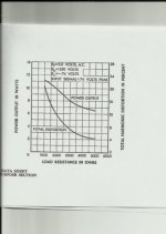
For triodes, a light load is always better, distortion-wise. 5xRa is just a good compromise between power and distortion. If I were using this for a preamp, I would use an active load
(infinite) which would then be in parallel with the following grid leak resistor. Distortion at low voltage swings would simply not be an issue.
Ah, bobik beat me to it.
(infinite) which would then be in parallel with the following grid leak resistor. Distortion at low voltage swings would simply not be an issue.
Ah, bobik beat me to it.
Member
Joined 2009
Paid Member
Well...I think even noobs like me understand that a higher load will usually reduce THD.
But 10×ra?
Citing a real tube, though not 6s19....the 6P6S likes anode losd at precisely 6k for minimum THD, below at 4k, and above at 8k, THD is almost double, and also changes in its spectrum. Its a similar story for 6P3S and many of the soviet valves I have experimented with (possibly many valves, or this is general behaviour)
Higher load, in that case gives lower 2nd, higher 3rd....bad news.
Lower load, the opposite effect, reduction of everything, except 2nd, which grows significantly.
So, I still disagree (go figure)
At some load point, between 3×ra and 6×ra there will be a sweet spot for THD.
If the observer, or article author, finds 3rd dominating THD at 6×ra, then I'd be willing to bet that at 3×ra the 2nd dominates, and the result sounds better.
The proof is in the pudding though, so the saying goes; so I'll hook some 6S19 up asap and see what the THD is saying.
Last edited:
Piano3,
Yes and yes I think I follow.
Certainly in triode, you cant dig as deep into B+ so you avoid areas where grid line spacing converged or diverged.
Do you mean WRT optimum load? I shall have to screenshot the data sheet, as the graph of K% vs Ra are within (and I dont recall if it is for triode or tetrode)
On another pentode, 6P30BR, in pentode SE, I anecdotally found a similar result when changing load.
Thinking on, I should have mentioned the caveat of "depending what the driver THD is doing".
Often I have come across THD spectra with 3rd dominating and all else at least 15dB lower.
The only time I have met a 3rd dominating and a long trail of upper harmonics, there was something wrong! (Such as a secondary snubber/RC loading the OPT)
Interestingly, when I have used a anode load CCS, the anode current has been the defining factor in the THD spectrum, or rather, finding the best quiescent current has been the most influential. But that's just DC load.
But running as many mA and as few V as possible, within ratings, doesn't fix it. (OPT AC load ignored)
I.e. theres still a balance?
I still had to optimise OPT load, to further improve the circuit -
So there is a dual balance, with CCS. DC load that gives the best result right off the bat, then OPT load that keeps V and I demands within the optimum AC load. Too much AC current demand (too low Ra), then higher THD across the board, mostly 2nd. And vice versa
I dont really know how to explain it. After all that.
Yes and yes
I think I follow.Certainly in triode, you cant dig as deep into B+ so you avoid areas where grid line spacing converged or diverged.
Do you mean WRT optimum load? I shall have to screenshot the data sheet, as the graph of K% vs Ra are within (and I dont recall if it is for triode or tetrode)
On another pentode, 6P30BR, in pentode SE, I anecdotally found a similar result when changing load.
Thinking on, I should have mentioned the caveat of "depending what the driver THD is doing".
Often I have come across THD spectra with 3rd dominating and all else at least 15dB lower.
The only time I have met a 3rd dominating and a long trail of upper harmonics, there was something wrong! (Such as a secondary snubber/RC loading the OPT)
Interestingly, when I have used a anode load CCS, the anode current has been the defining factor in the THD spectrum, or rather, finding the best quiescent current has been the most influential. But that's just DC load.
But running as many mA and as few V as possible, within ratings, doesn't fix it. (OPT AC load ignored)
I.e. theres still a balance?
I still had to optimise OPT load, to further improve the circuit -
So there is a dual balance, with CCS. DC load that gives the best result right off the bat, then OPT load that keeps V and I demands within the optimum AC load. Too much AC current demand (too low Ra), then higher THD across the board, mostly 2nd. And vice versa
I dont really know how to explain it. After all that.
Last edited:
the 6P6S likes anode losd at precisely 6k for minimum THD, below at 4k, and above at 8k, THD is almost double, and also changes in its spectrum.
...all at stable anode voltage. Pentode and tetrode amplify almost as Rl*gm, so when you increase load resistance, distortions go down, but amplitude goes up, and when it approaches clipping distortions increase. That graphs were taken for output stages, to get maximal output power with minimal distortions. When you are getting the same anode voltage swing, not the same grid drive, the picture is totally different.
Wavebourn,
I agree. Once voltage 'headroom' has gone, THD will increase again, due to clipping of one polarity swing vs the other.
Saying the picture is different, with similar outputs, but different grid input, is basically saying the THD spectrum will change, with a change in gain (the only way a different grid input will give the same output is if gain changes)
a noteworthy caveat in all a write is that I always use plate to grid NFB on the output stage. (Even, when I used a global FB loop, the plate to grid FB stayed in place, due to the impact is has on THD.)
This is just something I do to lower THD, and I dont think many others do the same - most prefer to run output stage open loop and pass the feedback to an earlier stage, in order to control excess gain, and reduce THD.
I have found it easier not going the route of feedback from output to driver stage, and in every iteration I have tried, local plate to grid FB on each stage beats it everytime for THD, and presumably output Z too.
Last edited:
- Status
- This old topic is closed. If you want to reopen this topic, contact a moderator using the "Report Post" button.
- Home
- Amplifiers
- Tubes / Valves
- 6S19P Amplifier