If it is indeed half of a 6080, then my experience may be useful.
I built a PP 6080 amp with toroidal output transformers and toroidals as interstage phase splitters.
I am running the outputs at 100V and 100mA (a good operating point). Grid bias is -30V which is relatively easy to generate. These valve are quite variable so Constant Current Sinks in the cathodes are nearly essential. I used a simple LM317 CCS from the Tubecad site. This restricts you to pure class A. I am driving 4ohm speakers and if memory serves correctly I am using 6V toroidals. I found that the output stage gave a less than unity voltage gain despite their MU of 2.
The use of toroidal interstage phase splitters have worked well but are very hard to drive satisfactorily. I rapped GNFB around them, and also have Plate to plate feedback from the voltage gain stage to the driver tube. The driver tube is ECL82 with a CCS load on the triode strapped pentode. This was mainly to conserve voltage headroom to allow the 60Vpp driver I needed. A better bet would be a seperate driver stage power supply with double the voltage needed for the output stage. This would allow you to use the interstage transformers as step downs to improve their high frequency bandwidth. Forget any ideas of using interstage transformers as step-up's, it just wont work - full stop. The ECL82 is the weakest part of the amp.
Overall I am very happy with the powerful but smooth sound this amp produces. The 6080's have given about 7 months of continues service at about 12hrs a day. I use delayed +B switch on which I think is of benefit when running the valves at such high current. This is the best amp I have built so far, but I am considering an upgrade of replacing the ECL82 with some PL84(EL86) drivers. I get about 7watts of power out.
Hope that helps.
Shoog
The way I usually calculate the plate to plate load is;
115V/6V=19.1666
19.16666 x 19.16666 = 367.36
367.36 x 4ohms = 1469ohms
Though I'am not certain if I shouldn't be using 12V as the ratio as that is the plate to plate loading.
I used 200R as the plate resistance.
Shoog
115V/6V=19.1666
19.16666 x 19.16666 = 367.36
367.36 x 4ohms = 1469ohms
Though I'am not certain if I shouldn't be using 12V as the ratio as that is the plate to plate loading.
I used 200R as the plate resistance.
Shoog
Well, I won a pair of 10K a-a transformers out of a Hammond organ:
http://tinyurl.com/2jd8dq
I think this project is back on track. I'd planned for 8K a-a in my most recent designs but this should be all right.
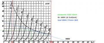
I see myself as having two choices: Fixed-bias or cathode bias. Either way, The output tubes will be biased at 220Va, -85Vg, 40mA each. The PT will probably want to be able to put out 200mA comfortably, assuming minimal variation in current draw (class A, after all). A question: How close to the 11W dissipation should I go? At the moment, I'm clearly only at 8.8W, or 80% of the max. I've read somewhere that 80% is a sweet spot between tube life and power?
Fixed-bias:
Rectify 250V into one choke for the B+ supply, and have another set of diodes rectify into a cap-input Pi filter for the secondary B+ supplies at around 350V or so. This should give enough headroom for 150V of swing. However, will needing to smooth an entirely different B+ line not be worth the hassle? As an option, I have a schematic for a decent-looking MOSFET-based regulator that spits out a clean 300V from 340V input...
Cathode bias:
350V PT. Choke-input rectify to hopefully around 310V, minus 5V for the OPT, and 85V for the bias resistors, to 220V on the plates just like before. Will a 100-ohm 2W potentiometer have enough range to adjust between mismatched tubes? I'd assume half its value, 50 ohms, in series with another 50 ohms, in series with a 2K 10W resistor for 2100 ohms total, which according to the datasheets should put me right at 40mA. Could I get away with bigger-value pots, i.e. how much power should I assume these will dissipate? Max current at the peak of peaks should be 90mA, so if a 100-ohm pot is turned all the way, it should still only dissipate .81W right?
Now, for the rest of the amplifier. 150V of swing is no mean feat, but here's how I was planning it: the phase splitter consists of two 6N2P's in SRPP, joined at the bottom cathode and made into a LTP, direct-coupled (Aikido-style?) to a standard 5687 grounded-cathode driver stage, which then feeds into the 6S19P's either by RC or by the fixed-bias.. One question is where to try to inject some NFB, if I ever want to. A fully differential triode amp probably won't need too much, though.
One concern of mine is heater current: four 6S19P's is 6.3V 4A, then four 6N2P's are 1.36A, then two 5687's are 2A - total 7.36A. Maybe I can rectify the unused 5A line off of a standard Hammond transformer and use an LM-type regulator for the 5687's and 6N2Ps? I'd just wire the 6S19P's out of phase and hope that's enough.
Sorry to bug you all with questions and I'll try to come up with a comprehensive design, according to which general layout sounds better. What do you think so far?
http://tinyurl.com/2jd8dq
I think this project is back on track. I'd planned for 8K a-a in my most recent designs but this should be all right.
I see myself as having two choices: Fixed-bias or cathode bias. Either way, The output tubes will be biased at 220Va, -85Vg, 40mA each. The PT will probably want to be able to put out 200mA comfortably, assuming minimal variation in current draw (class A, after all). A question: How close to the 11W dissipation should I go? At the moment, I'm clearly only at 8.8W, or 80% of the max. I've read somewhere that 80% is a sweet spot between tube life and power?
Fixed-bias:
Rectify 250V into one choke for the B+ supply, and have another set of diodes rectify into a cap-input Pi filter for the secondary B+ supplies at around 350V or so. This should give enough headroom for 150V of swing. However, will needing to smooth an entirely different B+ line not be worth the hassle? As an option, I have a schematic for a decent-looking MOSFET-based regulator that spits out a clean 300V from 340V input...
Cathode bias:
350V PT. Choke-input rectify to hopefully around 310V, minus 5V for the OPT, and 85V for the bias resistors, to 220V on the plates just like before. Will a 100-ohm 2W potentiometer have enough range to adjust between mismatched tubes? I'd assume half its value, 50 ohms, in series with another 50 ohms, in series with a 2K 10W resistor for 2100 ohms total, which according to the datasheets should put me right at 40mA. Could I get away with bigger-value pots, i.e. how much power should I assume these will dissipate? Max current at the peak of peaks should be 90mA, so if a 100-ohm pot is turned all the way, it should still only dissipate .81W right?
Now, for the rest of the amplifier. 150V of swing is no mean feat, but here's how I was planning it: the phase splitter consists of two 6N2P's in SRPP, joined at the bottom cathode and made into a LTP, direct-coupled (Aikido-style?) to a standard 5687 grounded-cathode driver stage, which then feeds into the 6S19P's either by RC or by the fixed-bias.. One question is where to try to inject some NFB, if I ever want to. A fully differential triode amp probably won't need too much, though.
One concern of mine is heater current: four 6S19P's is 6.3V 4A, then four 6N2P's are 1.36A, then two 5687's are 2A - total 7.36A. Maybe I can rectify the unused 5A line off of a standard Hammond transformer and use an LM-type regulator for the 5687's and 6N2Ps? I'd just wire the 6S19P's out of phase and hope that's enough.
Sorry to bug you all with questions and I'll try to come up with a comprehensive design, according to which general layout sounds better. What do you think so far?
This seems like a somewhat elegant solution. Buy an isolation transformer with dual primaries or secondaries, or both. Wire it so that you have 115V primary and two 115V secondaries.
1 bridge rectifier off the 240V (120V lines) goes to an almost-choke-input with a 3.3uF cheater cap to get 220V B+. Another BR goes to a full cap input supply which gets regulated to 300V or above for a good B+2 supply. For bias, I'd bridge-rectify off of just one of the 120V secondaries, then steal the layout from the Diytube Eiclone to get my voltages, adjusting a bit for the higher bias voltage.
Does anything seem intrinsically wrong from this approach? Allied Electronics has a 100VA transformer with just this configuration for a very reasonable price.
One concern of mine is heater current: four 6S19P's is 6.3V 4A, then four 6N2P's are 1.36A, then two 5687's are 2A - total 7.36A. Maybe I can rectify the unused 5A line off of a standard Hammond transformer and use an LM-type regulator for the 5687's and 6N2Ps? I'd just wire the 6S19P's out of phase and hope that's enough.
Rectifying the 5V winding just wont cut it. You can just about squeeze 6.3V DC from the 6.3 winding, but it doesn't work very well- even at moderate current draw. A seperate heater transformer seems in order. Consider a relatively easy to get 12V transformer and series connect two valves, run them slightly lean for longer life.
Shoog
3W output power per channel @ 16 ohms and 63W filament power consumption.
just a passing remarkj: I had a Krohn Hite lab OTL, consuming >250W for only 2 watt at 8 ohm but ohhh sooo nice; the best bass and mid tones I ever heard too on my Quad ESL57, and also surprisingly good bass grip on my TQWT.
It had 10 watt at the 20 ohm ESL and 50 watt at the 50 ohm of the bass region!
Made myself a 12b4A preamp some years ago, and I may be wrong, but the 6s19p can do the same job? Low gain is what I need. The 6s19p are cheap and the 12b4A are rare here i Europe. Have to pay about 25 US dollars for the postage for a pair from USA.
6s19p has only half the mu of 12B4a, which is already very low, if you can live with that ?
Otherwise there is a source for 12B4a in Europe though, 8.99 and ships for 7.50 Euros:
12B4A - 12B4 TUBE. MIXED BRAND TUBE. NOS/NIB. RC67. [141565532172] - €8.99 : RADIO-ANTIGUA, La tienda con los mejores precios y calidad de la red.
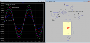
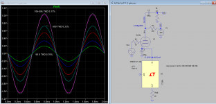
My 6S19P Linestage
Schematic image not found. So I came up with my schematic. The plate is 50V, current is adjustable (20m-60m) so as grid is biased between -5v to -8v, lowering bias reduce distortion when load is low. Zero feedback.
Schematic image not found. So I came up with my schematic. The plate is 50V, current is adjustable (20m-60m) so as grid is biased between -5v to -8v, lowering bias reduce distortion when load is low. Zero feedback.
Attachments
- Status
- This old topic is closed. If you want to reopen this topic, contact a moderator using the "Report Post" button.
- Home
- Amplifiers
- Tubes / Valves
- 6S19P Amplifier