Dynaco Mark VI help needed by a newcomer to tube amps.
Does anyone have information on converting the Dynaco Mark VI to say a kt88 or something better?
My goal is to replace the discontinued 8417 to something with the same power or better that is still in production today. I would also like to keep them at 120 watts or better. Any information would be greatly appreciated.
Thank you
Hi,
The Mark VI uses a 2200 ohm ct primary OPT. 4 KT 88's or 4 6550's will give the same relative output power with this OPT. Problem with using these substitutes is that they are not as sensitive to drive voltage as the 8417's are. This means that you will need to add an extra gain stage or redesign the amp's driver to achieve the extra drive voltage required when using the KT88 or 6550 tubes. Can be done but some / a lot of modifying will need to be done to the amps.
The 8417 was one of the last tubes to be designed and marketed before solid state took over. Good ones are great... a pair will output 100 watts with very little drive voltage. There are a lot of 8417's that are prone to thermal runaway; I can't remember what brand was bad about this, I think it was GE.
The 8417 closely resembles horizontal sweep tubes (6LQ6, 6JS6C, 6JE6, etc ) in performance and construction. The control grid is spaced extremely close to the cathode, hence the high sensitivity of these tubes (also this same reason causes the thermal runaway problem - unstable bias in some makes).
Technically, you could use these sweep tubes for the Mark VI without redesigning the driver circuit on this amp, but you would have to redesign the output section as sweep tubes do not like more than 200-250 volts on their screens. NO ULTRALINEAR OPPERARATION! Another problem with these sweep tubes is that they have become VERY pricey as they were used in the 70-80's in linear amps for CB's, etc.
Hope this helps...
Daniel
hey-Hey!!!,
The Mk.VI has the same front end as the MK.III (which runs 6550/KT88). It should have no issue driving any of the pin compatible tubes.
In the Dynaco case, it was not gain to cause troubles, it was limited voltage output. A long-tail-pair can swing a far higher percentage of its B+ compared to the split-load inverter.
cheers,
Douglas
I rebuilt my MkVIs using 6550 UL, diff cascoded 6DJ8s(CCS ith negative rail from bias-winding) and E182CC as CFs. I also had separate bias for each tube.
They where quite powerful even when driving a pair of ML CLSII.
If I had done it today I would have gone for triodemode and interstage transformer.
They where quite powerful even when driving a pair of ML CLSII.
If I had done it today I would have gone for triodemode and interstage transformer.
revintage said:I rebuilt my MkVIs using 6550 UL, diff cascoded 6DJ8s(CCS ith negative rail from bias-winding) and E182CC as CFs. I also had separate bias for each tube.
They where quite powerful even when driving a pair of ML CLSII.
If I had done it today I would have gone for triodemode and interstage transformer.
You can try a neat mod. Tie the diff amp plate loads to the U-L tap of the side they're driving. Eliminate the loop of NFB I bet you used. This is called E-Linear connection.
cheers,
Douglas
Thanks for the info so far.
Sounds like the way to go is to start with a Mark III upgrade board and add the second set of output tubes to that.
Avoids the drive issues that using the default board designed for the 8417 would introduce.
it does not sound like you can do enough to a Mark6 to make it behave correctly with tubes other than 8417's.
of course, ideas and comments are certainly welcome.
revintage said:Hi Douglas,
Forget about the mumbo-jumbo connections. Sold the junk over 10 years ago. And NFB is unfortunately necessary whatever amp you have when driving a pair of CLS. They where mean impedancewise.
There is a big difference between Loop and Local NFB. Local is what I proposed, even enough to deal with nasty, loopy impedance...
cheers,
Douglas
speakerfritz said:Thanks for the info so far.
Sounds like the way to go is to start with a Mark III upgrade board and add the second set of output tubes to that.
Avoids the drive issues that using the default board designed for the 8417 would introduce.
it does not sound like you can do enough to a Mark6 to make it behave correctly with tubes other than 8417's.
of course, ideas and comments are certainly welcome.
Search for the audioxpress article from Kara Caffee. There you will find an upgrade on the MK III circuit which will work extremely well for the Mark VI with 8417's or 6550/kt88's. I discussed this with Kara and the above was confirmed to work in the MK VI.
Further on the subject of the MK VI I recently purchased a pair which cosmetically was pretty beat up. They have good transformers and they came with Sonic Frontier upgrade boards which are exactly the same circuit as the MK VI Dynaco boards with upgraded parts.
I took one so far and did the following to it.
1. New PS caps in the second bank & bypassed with film caps.
2. Separate Bias supply control for each output tube.
3. 10 ohm resistor in each cathode to measure current via voltage.
4. Separate coupling cap for each output tube.
5. Separate grid resistors for each output tube and lowered to 39K from 47K.
6. 0.5A fuse in the CT of the PT.
7. Installed Sonic Frontier upgrade board.
8. Removed bias control from front panel.
Did a listen test this morning and all sounds real good. As I have found with all Dynaco units the voltages on the tubes even with new or as new tested tubes never seams to match the spec's in the manuals. Also there is always this "feedback" connection from one side of the OT UL tap to the driver board on all Dynaco amps with such OT. In the MK VI it goes to pin 5 of the driver board as shown in the attached schematic.
Can anyone give the real value of this connection?
Attachments
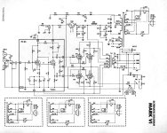
That feedback cap from the UL tap compensates for the fundamental primary imbalance in the (rather cheaply made) output transformers. You can adjust its value for a given feedback scheme by feeding in a 1kHz square wave, monitoring the output, and adjusting for equal ringing on negative and positive halves of the square wave (I usually use a ceramic trimmer cap in this position). Then adjust the RC network on the global loop to get the overall ringing minimized.
thx SY
One other question. Normally I would not be worried about this. It seems that not matter what set of tubes (8417) I put in I still get a different current reading on the side which uses this UL tap as feedback.
This can happen with a new set or a good used set. It happens on the rebuilt amp as well as the stock amp.
Any thoughts as to why?
Also since the rebuild amp has separate current adjust would you balance as normal here?
Thx again
- Status
- Not open for further replies.
- Home
- Amplifiers
- Tubes / Valves
- Dynaco Mark VI