Thanks everyone for the excellent advice, i'm kinda a noob with this design stuff I am a computer/network analyst and I have worked as a bench tech many years ago. So I have two schematics now. The goal really is to build an amp using the 117N7 to get that old time cheap crappy sound complete with the 60htz hum.
I am also interested in the PSE design and trying to make the 117N7 cleaner and louder but as has been said, a better tube would make more sense. Just for the education I would like to hear any comment on the basic design.
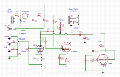
The integrated amp will be the final design, I plan to use the amp on an old RCA 45 changer with a ceramic high output cartridge, the one I have outputs 2.2V so I took the advice and added a driver. 5703WB sub mini tube. I also have a cheap USB player circuit board that I am building into the system it has headphone output so I will have to play with the input resistors to match the output levels.
I added an EM84 magic eye tube so have something to look at while listening. I am also thinking about adding a simple AM regen I am building to the system as well. The radio would most likely need a preamp tube before connecting to the selector switch?
I know the EM84 calls for 200V B+ but on bench testing I have got it working just fine with the 117V going to the 117N7. I have for this project a pre-built circuit board for the EM84 but I included the circuit shown to see what you think, I would rather be able to build my own next time.
On the PSE, is the reason for the 2K screen resistors, rather than 1K because the screens are connected in parallel? Would it be better not connected?
I am also interested in the PSE design and trying to make the 117N7 cleaner and louder but as has been said, a better tube would make more sense. Just for the education I would like to hear any comment on the basic design.
The integrated amp will be the final design, I plan to use the amp on an old RCA 45 changer with a ceramic high output cartridge, the one I have outputs 2.2V so I took the advice and added a driver. 5703WB sub mini tube. I also have a cheap USB player circuit board that I am building into the system it has headphone output so I will have to play with the input resistors to match the output levels.
I added an EM84 magic eye tube so have something to look at while listening. I am also thinking about adding a simple AM regen I am building to the system as well. The radio would most likely need a preamp tube before connecting to the selector switch?
I know the EM84 calls for 200V B+ but on bench testing I have got it working just fine with the 117V going to the 117N7. I have for this project a pre-built circuit board for the EM84 but I included the circuit shown to see what you think, I would rather be able to build my own next time.
On the PSE, is the reason for the 2K screen resistors, rather than 1K because the screens are connected in parallel? Would it be better not connected?
Attachments
A happy load for "plate load" will be the happy load for "cathode follower".
Ignoring the great difficulty of making the LARGE drive for a CF, which indeed may lead to a lower load Z to make the most of your small swing.
The Broskie plan is not a cathode follower. I do not remember why he drew a plate-loaded amp that way, with the battery and load moved around the loop.
WHY are you fascinated with 117N7? It is not a "good" tube. The only reasonable use is as a wall-power booster for a battery radio. 1T4 1R5 1T4 1S5 3Q4 ran on 90V B battery and 9V A battery. When you did some complicated switching, 117V wall juice powered all the above and a 117N7. Power output rose from 0.25W to 1 Watt and the battery was not drained.
Last edited:
The reason for wanting to use the 117N7 is because the project is kind of a steampunk project and part of the desired outcome is to replicate that cheap crappy hum filled sound that so many of the low end electronics of the 40's and 50's used. I believe the 117N7 is the pinnacle of this cheap sound. 117VAC heater bound to the internal diode, major hum, it's the ultimate cheap one tube solution. I did decide to add a tone circuit to kill some of the outrageous brightness. Most of the old cheap crap didn't even bother with that much indulgence.
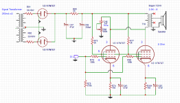
The PSE idea hit me when I thought that the 180 phased 117N7 tubes would cancel out the hum so I am just interest to see how well the tube could be made to sound. Unfortunately any attempt to add negative feedback made the gain almost non-existent so I don't see how it would get any better than this. Using very expensive "Audio grade" components would be pointless I assume. If anyone has any ideas i'd like to hear them. I am trying to keep the circuit simple.
The PSE idea hit me when I thought that the 180 phased 117N7 tubes would cancel out the hum so I am just interest to see how well the tube could be made to sound. Unfortunately any attempt to add negative feedback made the gain almost non-existent so I don't see how it would get any better than this. Using very expensive "Audio grade" components would be pointless I assume. If anyone has any ideas i'd like to hear them. I am trying to keep the circuit simple.
Last edited:
...to replicate that cheap crappy hum filled sound that so many of the low end electronics of the 40's and 50's ....
Would have been nice to say so sooner.
If that's the idea, why a C-R-C power filter with 250uFd at the end? The cheap crap used single 50uFd cap. That's likely more of "the sound" than where the heater is.
Use bad layout. This can be steampunked: curly leads outside the chassis.
For the parallel screens, either use a 1k dropping resistor and two 100 Ohm grid stopper resistors, or use two 2k dropping resistors (do not connect the screens together in either case). But the 2k resistors, or the 100 Ohm resistors need to be connected real close to the tube socket. this is to prevent oscillation, using a wire from the screen negates the stopper effect.
Paralleling tubes do not reduce any hum, they are not in opposite phase because it is not push pull. If the hum is from the filament to cathode leakage, and if that leakage is in opposite phase (no guarantee that the leakage is from one end of the filament in one tube and the other end of the filament in the other tube), then the hum might be reduced because to the parallel mode. But most of the hum from filament to cathode leakage is reduced by the cathode bypass capacitors.
Of course, bad placement of the filament wires to the control grid wires/parts can cause hum.
Post # 61
Left schematic has two 100k grid stopper resistors, use two 1k.
Right schematic has no control grid leak resistor to ground and no 1k control grid stopper resistor to pin 4, and no screen grid stopper resistor.
There also is signal from the input tube 47k plate load that gets on the 1k screen dropping resistor, 1/48th of the driver plate signal appears on the output tube screen (probably not a good idea). And there is no grid stopper resistor on the input tube control grid.
I hope you checked the calculation of current, and voltage, and resistor values of the input tube versus tube curves.
You are making changes so fast, it is hard to keep up. Get one design set and stabilized.
I have enough moving targets in my own amplifiers to chase.
Last edited:
I apologize for all the changes, i tend to be unfocused I guess, the picture on the right will be the final design. I will repost with your recommendations. I do wonder though why you are saying I need grid stop resistors. I have gone over a lot of tube amp designs and I don't see any of them with grid stop resistors. The 47K resistor should go directly to B+, I didn't think about it being seen on the screen.
As for the design on the left I am just curious about PSE and I don't understand what advantage PP has over PSE. I have read that single ended is more "pure" than PP so that is why I am looking at it and will probably use it in another amp design some where down the road.
As for the design on the left I am just curious about PSE and I don't understand what advantage PP has over PSE. I have read that single ended is more "pure" than PP so that is why I am looking at it and will probably use it in another amp design some where down the road.
Last edited:
Grid stoppers short out RF interference. Make sure it is right at the grid valve pin.
Without it you can get local radio coming through your setup.
I had a TDA7294 with valve pre amp and if the TDA7294 oscillated it radiated back into the pre amp ! A 47k and 100pf at the grid sorted it out.
Without it you can get local radio coming through your setup.
I had a TDA7294 with valve pre amp and if the TDA7294 oscillated it radiated back into the pre amp ! A 47k and 100pf at the grid sorted it out.
Thanks, you guys really know your tube designs, but the question still remains, why have I not seen these grid stoppers before in any of the tube amp designs I have looked at? Even the very high end designs.
For example look at any of the tube amp designs at this link you will not find any with grid stop resistors.
DIY and Hi-Fi Audio Schematics
I'm not trying to be argumentative I just wonder why.
For example look at any of the tube amp designs at this link you will not find any with grid stop resistors.
DIY and Hi-Fi Audio Schematics
I'm not trying to be argumentative I just wonder why.
Thanks, you guys really know your tube designs, but the question still remains, why have I not seen these grid stoppers before in any of the tube amp designs I have looked at? Even the very high end designs.
For example look at any of the tube amp designs at this link you will not find any with grid stop resistors.
I'm not trying to be argumentative I just wonder why.
You often don't need them. Have a look at this design: Vixen (attached). Here, you see the stopper resistors connected to the screen of the 807s. This type is liable to Barkhausen instability at plate current cutoff. (The other solution would be a low positive bias on the beam formers/suppressor grids, not possible here since the beam formers are internally connected to the cathode). You need these stoppers to swamp out a negative resistance that can appear at the screens and would cause a burst of high frequency oscillation (in this case ~60KHz). You also need plate stoppers as the type likes to make RF. Other types like the 6V6-oids don't have this problem.
You also see a grid stopper at the grid of the first pre. This is included to form a 1st order LPF with Ci + CMiller to keep incidental RF out of the signal chain (My QTH is very noisy due to a 50KW clear channel AM xmtr 30 miles away.)
Attachments
The reason for wanting to use the 117N7 is because the project is kind of a steampunk project and part of the desired outcome is to replicate that cheap crappy hum filled sound that so many of the low end electronics of the 40's and 50's used. I believe the 117N7 is the pinnacle of this cheap sound.
Your project is suffering from scope creep. Your goals and what you have designed are now in conflict with each other. If your goal is to see how it performed back then I recommend you just build the original basic circuit.
After that measure output, hum and frequency response and see how you like it. Try it with different speakers and see what you like and what, if anything, you would like to improve. Your output transformers will probably couple WAY more hum into the speakers than the tiny stock transformers used with these would have. Try a regulated B+(or a choke filtered supply) later, it's easy to change if you lay it out with the intention of messing with it later. Not enough drive from your source? Add either another tube or add an input transformer. Even a tiny audio input transformer will sound great at the low currents the grid circuit will be running at.
I'm currently working on a 'similar' project but it is a dual 60FX5 stereo single ended pentode amp. First build was directly out of the RCA manual(isolation setup of course). Sounded fine, hummed a bit but that's to be expected with the low-end designs. Leaving the entire amplifier circuit itself alone I am re-doing the power supply to have a solid state regulated B+ and DC heaters. When that is done I will see what I want to do next with it, if anything. I have my next couple of series string victims lined up with a 50FX5/20EZ7, 34GD5/20EZ7/36AM3, 32ET5/18GD6, and even a 117L7GT amp which is the lower voltage and lower output brother of the 117N7.
As for grid stoppers and such, it's true that you often don't need them but like a lot of things it's nice when you have them. For example, polarity protection diodes on DC equipment. It's not necessary most of the time but that one time you connect power backwards and trash a 30 year old device that can't be replaced you'll wish you had that 2 cent diode in there.
Last edited:
You never need a grid stopper until the amp oscillates because you left it out.
Start with a tube amp schematic you find on the web.
A large percentage of them have never actually been built; but many have been duplicated many times.
But, lets use one that has been built and was tested and worked good.
How will you place the wires on your version exactly like the one that was built successfully?
Did you use a different output transformer, and you are using negative feedback?
Are your tubes just like the amp that worked good?
What "little" modification did you make from the working amp?
Was the working good amp marginally stable, and it did not get tested by using it on your challenging inductive reactance and challenging capacitive reactance loudspeakers which also have a nasty low impedance dip at some frequency, and extremely high impedance at other frequencies?
Do you have a scope that covers all possible frequencies of oscillation?
Do you have a scope with FFT or a spectrum analyzer, and a low distortion oscillator or a CD with precision signals?
If the amp sounds bad, is it a fundamental flaw, or does it not work well with the rest of your system?
...For example look at any of the tube amp designs at this link you will not find any with grid stop resistors.
DIY and Hi-Fi Audio Schematics ....
Half the first dozen links on that page have grid-stopper somewhere.
4S Universal Preamplifier for 12A*7 Tubes
DIY ECC802S (12AU7 / ECC82) Vacuum Tube SRPP Preamplifier
DIY 5687 Vacuum Tube Hi-Fi Preamplifier (LED Biased)
Groovewatt a DIY Vacuum Tube (Valve) RIAA Phono Preamplifier Project
http://diyaudioprojects.com/Schematics/SE-2A3-Tube-Amp-Schematic.htm (Rx)
http://diyaudioprojects.com/Schematics/Mullard-SE-EL84-Tube-Amp-Schematic.htm
Damn, you're right. I never noticed them before. It never occurred to me that is what they were there for, but I see them clearly now. You guys are good. I really want to thank all of you, I'm learning more in a few days on here than I have just trying to figure it out on my own for months. I am starting to realize these are not just the simple circuits they appear. I have a lot of misconceptions on design.
So how do you know when a grid stopper is needed when designing a circuit? Is it best to just always use them? Better to have them and not need them? How would you test the circuit to see these oscillations? It sounds like they would be frequencies that I never look for.
So how do you know when a grid stopper is needed when designing a circuit? Is it best to just always use them? Better to have them and not need them? How would you test the circuit to see these oscillations? It sounds like they would be frequencies that I never look for.
...So how do you know when a grid stopper is needed when designing a circuit?....
How much does a 12-cent resistor cost?
How much does hours of debugging cost, in salary, lost pleasure, or hair?
I have my next couple of series string victims lined up
The 20EZ7 has become rather scarce because it was used in guitar amps years ago. Make sure you can get a couple before going down that road. I have a guitar amp using an 18FW6, an 18FY6 and a pair of 32ET5's. It will make 4 watts on a 165 volt supply. If you choose to ignore the ratings you can get 10 watts in cathode biased AB1 from 330 volts. 20 watts requires fixed bias AB2.
Need more power, the 45B5 / UL84 will make 20 watts in cathode bias from 330 volts within the ratings. All are 100 mA heaters.
How much does a 12-cent resistor cost?
How much does hours of debugging cost, in salary, lost pleasure, or hair?
I pay 1.1 cents CAD for a 1/2W MF resistor... I also bought a lot of 6000 which helps.
The 20EZ7 has become rather scarce because it was used in guitar amps years ago.
I was actually surprised at first at how difficult getting some of these tubes would be. 20EZ7 wasn't too bad the but 50FK5 was fun to track down as I don't think it was used much at all. The 60FX5 was at least used in a handful of radios so it wasn't bad.
- Status
- This old topic is closed. If you want to reopen this topic, contact a moderator using the "Report Post" button.
- Home
- Amplifiers
- Tubes / Valves
- 117v heater tube 117n7