I don't use the power rails I usually pin the power directly to the circuit in the bread board space, i never thought about the breadboard power rating. I am using an isolation transformer and a variac. Is there a breadboard you all recommend that I should be using? Is what I'm doing dangerous?
Keep the B+ level items in their own breadboard half and it should be OK. That 36V rating is between pins adjacent to each other so each half of the breadboard is a potential arc hazard only for that half. So for example a triode would have heater, grid, and cathode on one half and the plate on the other half so the tube is straddling the board like an IC would if you plugged it in. The only problem that doesn't solve is arcing across the aluminum mounting plate.
The 36V rating is not additive. You can't assume that B+/36V is going to give you safe spacing.
The 36V rating is not additive. You can't assume that B+/36V is going to give you safe spacing.
Last edited:
A piece of plywood and sockets that have accessible pins when mounted to the plywood.Is there a breadboard you all recommend that I should be using? Is what I'm doing dangerous?
Keep the B+ level items in their own breadboard half and it should be OK.
This is probably a good idea. I usually take this a step further. I had one of those pre - made assemblies like yours, but I used it mostly for IC and discrete designs as it was intended. It was used when I got it at a hamfest, and eventyally became intermittent. I tried to pry the modules from the metal backing plate......don't. The thin double sided tape that holds the strip to the metal plate also holds the 5 way metal contacts in place. Once disassembled, they don't go back together well, so I tossed it.
After not using one for years I bought some of the plastic modules from Amazon. They look just like those in your picture. I got several of these mostly for Arduino compatible Teensy and Blue Pill designs, but I have used them for tube circuits.
The only problem that doesn't solve is arcing across the aluminum mounting plate.
The only insulation between the actual metal contact strips and the metal plate is the double sided tape. It should withstand considerable voltage before breaking down, IF it is in good condition and has not absorbed moisture. These can not be guaranteed, therefore my additional polycarbonate sheet.
for example a triode would have heater, grid, and cathode on one half and the plate on the other half so the tube is straddling the board like an IC
Excellent idea. Tube circuits tend to be large, so it is possible to use separate breadboard modules for each half. I have done this, but mostly because it was easier when octal sockets are involved. There are other issues to overcome, so I tend to use these things for rather low powered stuff if at all on tube circuits. Assume that the entire module is hot with full B+ and use extreme care when poking around in a live circuit.
These things will not eat a 2 watt resistor lead very many times before a 1/4 watt resistor will no longer make reliable contact.....the reason for tossing my first breadboard. Ditto many coupling caps.
Heater current......you can't run the heater current through the contacts unless you are dealing with low currents. 300 to maybe 450 mA max. I tend to wire these directly to the tube socket with clip leads or soldered wire.
Keep in mind that any time you put an inductive load on a tube (an OPT or IT) the plate voltage can swing to twice the B+ voltage under normal use, and maybe 4 X B+ on an overdriven guitar amp.
I still prefer using perf board or Vector board for tube designs, especially now that you can get cheap knock-offs from China.
I use these. I put one stage on a board, then interconnect the boards to make a whole amp. These can be found at Amazon, in stock with Prime for about $3 to $4 each. Larger ones are available. Direct ship from China is around $1 to $2 each in quantity. I got a batch today, total time 2 weeks. Single sided boards are cheaper, and are fine for a through hole design. The double sided versions are better if limited SMD's are used.
Robot Check
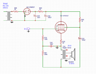
As-is that circuit is an excellent way to destroy tubes. You grounded the wrong side of the output transformer so the only thing in series with the tube is the 30 ohm cathode resistor.
That's also not inverted mode, it's cathode follower. It will require a very large input drive voltage and that 5K:8 will no longer be appropriate.
That's also not inverted mode, it's cathode follower. It will require a very large input drive voltage and that 5K:8 will no longer be appropriate.
I modified the circuit from this floating power supply inverted circuit from Tubecad, its not a cathode follower. I value any input, the concept looks cool but is this something not worth trying?
He posted this:
Here we see the EL34's supporting circuitry and the floating power supply fleshed out a bit. Where to start? The 10k screen resistor seems to be in parallel with the load impedance; it isn't, as it sees a fixed DC voltage and all the AC power-supply noise. The 0.68µF capacitor connected to ground is there to filter away the output transformer's huge 250V voltage swings from the grid circuit. Remember the output transformer's primary will swing both hugely negatively and positively, but the average should equal the idle state's nominal -32Vdc. The 30-ohm cathode resistor is there to add some resistance to the output transformer's primary's DCR and to allow easy measurement; besides, it linearizes the output tube a tad. (The real reason it's there is that I envision three EL34s working in parallel, with a UBT-1 output transformer with a DCR of 160 ohms; and I want to prevent current hogging by any of the output tubes.)
Attachments
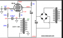
Ahhhhhh, the problem in your schematic is you grounded the power supply. It's supposed to float.
Ignore the part of my post about the transformer. I don't know nearly enough about this circuit or mode of operation to comment on that other than the fact that DCR will be important since it biases the tube.
Ignore the part of my post about the transformer. I don't know nearly enough about this circuit or mode of operation to comment on that other than the fact that DCR will be important since it biases the tube.
Last edited:
Blaxshep,
You want to use 3 each EL34 in parallel single ended and a UBT-1.
A UBT-1 primary to 8 Ohm output has a 14 to 1 voltage loss (not power loss).
A Cathode follower has a voltage gain of less than unity (less than 1).
Using a cathode follower and UBT-1 and no input gain stage before it
will not have enough gain.
3 parallel EL34 tubes in pentode mode has too high of a plate resistance to work with a UBT-1 for anything except to use it as a guitar amplifier. And it will not have enough gain to use with the low output guitar pickup. It will have some gain, but the damping factor will be very low, the distortion will be high, and frequency response will not be good.
3 parallel EL34 tubes in triode mode has low enough plate resistance to work with a UBT-1.
But the gain will be low, perhaps 7 from the tubes, and 1/14 from the UBT-1, the total gain will only be 1/2. 3 Volts peak from a CD player will only give 1.5V peak to the loudspeaker. And it will not have enough gain to use with the low output guitar pickup.
Your posts 46 and 48 are wrong.
The plate is not driving the output transformer.
The cathode is driving the 30 Ohm resistor.
There is nothing driving the output transformer.
What will you use the amp for?
How much power do you need?
What is / are the signal sources?
What is the loudspeaker load?
Hi Fi or guitar amp?
Then we can find what modifications you need to get there.
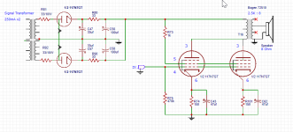
OK, what I am trying to do is make the 117N7, which is said to be crap, into a good sounding and safe mono block amp to power an old RCA 45 turntable or a usb, etc, ... So I was thinking if I had two 117N7 PSE I could put them out of phase to cancel the 60Hz noise and come out clean with 2W output. I think in PSE the 5K output transformer would be 2.5K instead of the 5k for a single tube, Im giving up on the inverted, floating based on the responses here, so what do you think about this design?
Attachments
Blaxshep,
If you have the power transformers connected in the right phases, then you have a full wave B+ supply.
The main ripple will not be 60Hz anymore, it will be 120Hz, but it will be much better filtered.
You can connect one filament per secondary (you did not show the connection dot).
The gain in this circuit is because the tube is conected in pentode mode.
The parallel connection might be subject to oscillation.
Use two 1 k Ohm control grid stopper resistors, connected right up at the tube sockets, and the other ends connected to R75 and the input. And use two 2k Ohm screen resistors, one for each screen.
2.5k for two tubes is the same as 5k for one tube as far as the current per tube, and as far as the primary voltage swing.
But the output transformer needs to work with 2 times the current.
The transformer must be a single ended type, i.e. a Hammond 125SE series (is the Bogen for SE or for push pull?).
There will be no effective damping, i.e. for a traditional 2 way bass reflex or acoustic suspension speaker (because of the pentode mode that gives the gain).
There will not be very much gain, these kinds of circuits were used with what was basically an efficient midrange driver, and a high output crystal or ceramic cartridge in the turntable.
Last edited:
OK, what I am trying to do is make the 117N7, which is said to be crap, into a good sounding and safe mono block amp to power an old RCA 45 turntable or a usb, etc
If you're going to do that, then you're better off using the integral diodes as a proper Full Wave circuit, and connect the pentode halves as a PP output stage. You could split phases with an IST at the input which could also give you some voltage gain. These pents aren't exactly intended for sonic quality, given the intended uses. Coming in at 6.28% isn't all that great, but it's not terribly out of line for this type of application. As to how that sounds, if it's mostly h3 it might be a bit on the "aggressive" side, but you may like that for some material. If there is a lot of h5 and higher, it'll sound pentode nasty without any NFB to clean up the harmonic messes.
There wasn't any plate characteristics for the 117N7, but the 117L7 seems to be identical except for pin-out. Loadline attached.
Attachments
A piece of plywood and sockets that have accessible pins when mounted to the plywood.
Mine are like this. They are actually from a local bakery, and originally came with a very large, fresh baked loaf of bread on them.
Serious! This is always what I think breadboarding is.... you need a board from the bakery... maybe I have been living in Europe too long?
The little boards that people have posted are what I would call experimenter boards. For that I have proper glass fiber once from the local supply. They look somewhat similar to what tubelab posted earlier (perhaps my connections are not quite as curvy as his though).
Those boards where you plug stuff into are bad news. I think I had a few as a kid for battery circuit kits, etc. I would never use them to experiment with any valve/tube circuit.
Last edited:
Blaxshep, your biggest problem with using only this tube alone is going to be drive voltage. Even headphone outputs run ~3.3V signals and to fully drive this pentode you will need a 6V signal.
Now, there IS a way to use some of the waste from this guy to get that drive and still use tubes. The 50mA running current of the 117N7 is convenient because you can sub the heater of a 1U4 battery pentode for ~30 ohms of your cathode circuit and run a gain stage. This would also allow you room for feedback which would clean things up too. Since the 1U4 only wants to see about 90V at 1.5mA there is plenty of room to make quiet B+ for it.
If you want to go with a push pull circuit you can still run the 1U4 heaters but you might need to shunt extra current. Not sure how you'd setup a directly heated phase splitter but I'm sure someone here knows. There is self-split push pull but it isn't very efficient at much more than getting rid of 2nd harmonics.
Last edited:
Blaxshep,
Yes, for push pull, you might as well either go triode wired and no negative feedback (lower power), or pentode mode and use negative feedback. But these do not have enough gain, so the extra gain stage, and phase splitter is needed.
It is not easy to apply negative feedback to a simple push pull circuit when using an input interstage splitter without an added balanced or differential tube gain stage. And the interstage will have to be driven by a low impedance signal source.
By the time you make a working circuit of 117V tubes that will have gain, power, and low distortion, you have made the amp complex enough that you might consider other tubes:
Unless you are really wanting and requiring this to be a 117V filament pentode circuit, you might consider some other amplifier configuration . . .
Push Pull or Parallel Single Ended, with maybe a pair of 6V6s, EL84s, 6CK4s, 6BX7s, 807s, or many other tube types, plus a dual triode input stage for gain and phase splitting for push pull; or a single triode for gain in a parallel single ended amp.
"You should make things as simple as possible, but no simpler" . . . Albert Einstein
Last edited:
- Status
- This old topic is closed. If you want to reopen this topic, contact a moderator using the "Report Post" button.
- Home
- Amplifiers
- Tubes / Valves
- 117v heater tube 117n7