Hi everyone,
I have obtained this little vintage amp on ebay and would like to fix it.
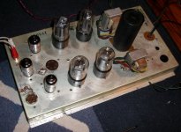
As you can see its very old amp, which by the way uses no power trafo, its hooked strait to mains. Not very safe, I know, I will use isolating trafo in the future, for now its hooked to variac.
Anyway, I replaced power supply capacitors and put connectors on input. One chanel is loud and clear, the other is quiet and distorted. I swapped tubes between chanels and measured all the pasive parts, do not see any difference between the chanels.
I need your suggestions, please help me fix this amp. It seems simple task, when one chanel is working and other not, but I got no idea what to do and been stuck like this.
It uses 12AX7 as preamp and splitter tubes and 25L6 on output.
Here is picture.
Thanks,
ed
I have obtained this little vintage amp on ebay and would like to fix it.
As you can see its very old amp, which by the way uses no power trafo, its hooked strait to mains. Not very safe, I know, I will use isolating trafo in the future, for now its hooked to variac.
Anyway, I replaced power supply capacitors and put connectors on input. One chanel is loud and clear, the other is quiet and distorted. I swapped tubes between chanels and measured all the pasive parts, do not see any difference between the chanels.
I need your suggestions, please help me fix this amp. It seems simple task, when one chanel is working and other not, but I got no idea what to do and been stuck like this.
It uses 12AX7 as preamp and splitter tubes and 25L6 on output.
Here is picture.
Thanks,
ed
Attachments
You might check the output transformers to see if a winding is shorted or open, and if possible, wire the working side's OPT to the non-working channel to see if that works.
Taking voltage measurements from 0 to plates and cathodes on all tubes, as well as other voltages, might help people here to diagnose.
You probably know this already, but most variacs are autoformers and do NOT isolate. Be very careful and drain all your caps as well after you unplug.
--Jeff
Taking voltage measurements from 0 to plates and cathodes on all tubes, as well as other voltages, might help people here to diagnose.
You probably know this already, but most variacs are autoformers and do NOT isolate.
Be very careful and drain all your caps as well after you unplug.--Jeff
hi Zibi, I have inspected all the solder joints and wires visualy, maybe I should resolder bad looking ones.
Jeff, I believe output trafnsformers are good, both measure the same resistance on primary and secondary for both chanels. I compared resistances on both chanes, I see no difference.
Yes, I know, my variac is autoformer too.
I am going to measure voltages.
ed
Jeff, I believe output trafnsformers are good, both measure the same resistance on primary and secondary for both chanels. I compared resistances on both chanes, I see no difference.
Yes, I know, my variac is autoformer too.
I am going to measure voltages.
ed
It is a good idea. Check also volume potentiometer and coupling capacitors.adason said:hi Zibi, I have inspected all the solder joints and wires visualy, maybe I should resolder bad looking ones.
ed
Don't plug anything into it except for a battery operated CD player or similar until you have an isolation transformer. The circuit is probably isolated from the chassis... but only by a 50-year-old capacitor, which is probably leaky... as are the remaining capacitors.
If there's a model number, I'll check the Sams index and see if I can turn up a schematic.
If there's a model number, I'll check the Sams index and see if I can turn up a schematic.
success! sweet success!
yes, yes, it was a capacitor, not in the power but the one from splitter to output tube
first I measured all the voltages and there were significant differences between the chanels
than I noticed that one big mp capacitor has a crack in its cover.
I unsoldered it and while its capacity was still ok, 68 nF, it was partly shorted, 150k ohm...
so I replaced it, and the chanel works!
Thanks all for your help!
I am sooner or later going to replace all the capacitors, even they are nonelectrolyts.
Than I am going to draw the schematics, maybe we can tweek it. Its playing both chanels happily now. Thanks,
ed
Adason,
The 25L6 draws 300 mA. of heater current. In a series heater string, like your amp uses, all heaters must draw the same current. That means the 12AX7 heaters are set up for 6.3 V./300 mA. So, the total requirement of the series string is 112.6 V. The higher "average" line voltages encountered today can be putting a stress on the tubes. A 24 Ohm/5 W. metal oxide resistor, that costs about $0.50, added to the series string will make the total voltage requirement 119.8, which (IMO) is better.
I'm assuming the amp's B+ is 1/2 wave Selenium rectified. Selenium rectifiers are ticking TOXIC time bombs, that must be replaced by modern Silicon parts. Adding an isolation trafo to the amp makes things MUCH safer and it gives you the option to full wave bridge rectify the B+. A "typical" operating point for PP 25L6s shows 25 mA. idle current per tube. A Triad N-68X isolation trafo, which costs about $11.25, will easily provide the B+ current 2X 12AX7s and 4X 25L6s draw. You are safe enough with the series heater string connected directly to the AC mains, as long as a DPST power switch (1 leg for heaters and 1 leg for B+) is used. Separate fuses for each switch leg are required.
Following Tom Bavis' recommendation of using only a battery powered portable CDP as the source until an isolation tafo is installed is MANDATORY. Until the iso trafo is installed, connecting to an AC mains powered source is DEADLY DANGEROUS.
Hi Eli and others,
great advice, thanks. I am going to do all that. I have isolation trafo ready. Rectifier will be next.
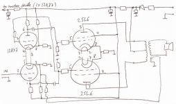
Here is the schematics as I tried to follow the amp. First triode is not there because I am not using it, too much gain. Let see what you think of it. Otherwise it sound nice, euphoric, just like I expected.
great advice, thanks. I am going to do all that. I have isolation trafo ready. Rectifier will be next.
Here is the schematics as I tried to follow the amp. First triode is not there because I am not using it, too much gain. Let see what you think of it. Otherwise it sound nice, euphoric, just like I expected.
Attachments
I found a GE 39851A listed By Sams... unfortunately, it says "photocopy", so it isn't in their normal series. So it WON'T be found in the usual places.
Looks like a paraphase splitter (see Magnavox) - but you may have a few parts transposed in your sketch... output of driver (inverted) goes to a voltage divider to feed opposite side of push-pull.
Looks like a paraphase splitter (see Magnavox) - but you may have a few parts transposed in your sketch... output of driver (inverted) goes to a voltage divider to feed opposite side of push-pull.
Adason,
My heater string calculation did not allow for a 3rd twin triode. If you add the 24 Ohm power resistor, disconnect the "inactive" twin triode's heater from the string.
The circuit you have drawn looks like a paraphase splitter to me. For good reasons, that topology is currently viewed with suspicion. However, the paraphase topology does provide gain along with splitting the phases. An alternative to paraphase that also provides gain is the long tailed pair (LTP), which is basically a differential circuit. To use a LTP, a B- supply rates to be needed.
It seems the "bean counters" worked hard on that amp. The separate NFB winding on the O/P trafos increased costs there, but it allowed the speaker to be electrically isolated from the potentially lethal chassis. Spend more on the O/P trafos, while realizing overall savings by not having a power trafo. Such techniques are no longer legal.
How far are you willing to go in tweaking the amp? 6922s would make reasonable LTP splitters. You would need the gain a 3rd twin triode provides, as the 12AX7 paraphase has MORE gain than a 6922 LTP does. A 3rd 6992 shared between the channels should do the job. Another possibility is to employ an 0B2 gas regulator tube in the 25L6 screen grid B+ supply. Regulated screen grid B+ would reduce the amount of intermodulation distortion the 25L6s generate.
hi Eli,
first thing I am going to do, most likely upcomig weekend is taking care of isolation trafo and selenium rectifier. Than I might replace remaining capacitors, especialy because one was wrong already.
Next I will put volume control and replace heater of unused triode with resistor. Some case would be nice as well, but I am not going to overdo it. I still do not know what I am going to use amp for.
At this point I am not sure if I want to go as far as changing tubes and topology. I have started to read more about paraphase splitter, maybe that why I like this amp so far, it has high distortion, but its euphoric.
ed
By the way, I have restored an old Magnavox push-pull amp from console similar to the one at web page below and I love it! It seems I am not the only one who likes the sound of paraphase splitter. Here is someones page:
http://gabevee.tripod.com/maggie.html
http://gabevee.tripod.com/maggie.html
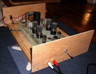
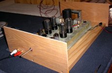
I have replaced rectifier and remaining caps. Unused first triode disconected. Amp is just siting in wooden box, to allow easy access.
Most importantly it has isolation trafo now, even the fuse!
Anyway, I have been playing it for some time now, and it sounds great. I have tested the amp with low efficiency speakers and it can play relatively loud and has an ok bass extension. However, I intend to use it with high efficiency full range speakers. Problem is, there is buz. Not too loud, but noticable with highly efficient speakers on quiet pasages.
How do I get rid this remaining buz?
Thanks for help.
ed
Attachments
Hi Eli,
the isolation trafo has only two wires on one side, two wires on the other, its original isolation trafo, thats what it says on it. However, only two wire power cord is used, so there is no "ground". Well, at least its isolated from mains by trafo.
Metal chasis, as far as I know, is not connected anywhere, its just floating.
No, there is no full wave rectifier. Just as shown in schematic few posts above. Amp had just one selenium rectifier which I replaced with silicon diode (450 volt, 3A).
So what do you say, could it stay this way? Or should I use three lead mains power cord and connect it to metal chasis? Many small power audio instruments use on two leads power cords.
How to tackle the buz?
ed
How do I get rid this remaining buz?
Buzz could be ripple from the B+ PSU. Consider changing the PSU filter to CLC. You use 2 of 3 spatial planes for the lam. stacks of the "iron" already in place. Mount the filter choke on the back wall of the chassis to place its lam. stack in the 3rd spatial plane.
- Status
- This old topic is closed. If you want to reopen this topic, contact a moderator using the "Report Post" button.
- Home
- Amplifiers
- Tubes / Valves
- vintage tube amp repair help