On my SS power amp, I inserted a snubber network between the switch and the primary of the transformer. It simply consists of a 0.22uF cap in series with a 100 ohm resistor both in parallel with the live and neutral of the transformers (the cap on the "+ve" side, resistor to "-ve" side).
I was told that this may lengthen the live of the switch AND prevent arcing on switch-off.
Anyway, would this work (and be necessary) for the Aikido preamp, which uses 115V AC to a Hammond 125-0-125 transformer, as well as Hammond 6.3V transformer?
Thanks,
Charlie
I was told that this may lengthen the live of the switch AND prevent arcing on switch-off.
Anyway, would this work (and be necessary) for the Aikido preamp, which uses 115V AC to a Hammond 125-0-125 transformer, as well as Hammond 6.3V transformer?
Thanks,
Charlie
This method works with essentially any switch or relay contact that is required to interrupt an inductive load. It not only limits the arcing damage to the switch contact, but also aids in limiting steep rise times, and in small measure limits transient voltages generated by the transformer. These transients are not friendly to turn-turn insulation.
The selection of C and R are determined from the maximum voltage to be interrupted and the expected maximum current. These equations are easily found on the websites of relay manufacturers (Aromat, P&B Tyco, Schrack, etc.)
For a low power circuit such as a preamp, you will likely end up with a small C and large R. Both C and R will need a fairly high voltage rating, depending on where your switch is located.
Zigzagflux,
Thank-you for the reply. I have searched the manufacturers that you suggested but did not find any method of calculating what I require.
Of course, I am planning that the on-off switch will only switch on the 6.3V heaters, while allowing 115V to flow to an Amperite 115NO30 tube relay, which will switch on power to the Hammond 150-0-125 transformer. So I suppose that I would also need the C-R arc-supression across the switched pins of the relay as well???
Anyway, if anyone has the relevant formulae, please reply.
Regards,
Charlie
For starters, try this out:
http://www.just4sheep.com/5988-6917EN.pdf
If you need more, just ask. Don't get too concerned about finding the 'perfect' value, especially if you're just interested in contact protection. I use these parts quite a bit:
http://www.alliedelec.com/Search/Pr...C=104M06QC100&R=852-7510&sid=456CCD802685E17F
Cheers.
I wish I still had the old Amperite ap note... they suggested using a latching relay with the delay tube, with the heater powered though a normally closed contact... this has a few advantages over using the delay tube alone:
1) heater is only powered during warmup - lasts a lot longer.
2) If contacts bounce (they DO...) - it doesn't matter, as relay has already latched.
3) If power is interrupted briefly, you get a full delay cycle without waiting
4) And of course, the relay handles the load - the delay tube only has to carry relay coil current.
Tom,
OK, so how does the latching relay work? I assume that when the time-relay is activated, time counts down and the Amperite relay switches on power to the latching relay. The latching relay requires only a brief power-up to trigger its relay - hence 115VAC to transformer and B+!!!!
So, how does the power to the Amperite get switched off? Afterall, the latching relay is supposed to save having to have continuous power applied to the Amperite tube relay? Maybe a second relay after the latching relay that switch power off!
I have noticed that latching relays are quite cheap - $8 or so.
Also I did buy NOS of the Amperite 115NO30 which was $20. What is the life span of these under continuous load? It is quite possible that I can buy a couple of spares.
Now, I am also assuming that the Amperite 115NO30 handles 115V (this is quite obvious from the datasheet). However, what is not obvious is whether it handles 115V to the heaters (I think it must).
Thanks,
Charlie
So, how does the power to the Amperite get switched off?
Charlie,
Head over to the nearest "Rat Shack". $8.49 gets you a Catalog # 275-217 DPDT relay with 10 A. contacts and a 125 VAC/15mA. coil. Wire 1 "leg" so the B+ trafo is energized when the relay is latched. Wire the second "leg" so the Amperite time delay is energized when the relay is unlatched. Wire the latched contact of the 2nd "leg" to energize the 275-2117. Wire the Amperite's contacts to energize the 275-217.
When the on/off switch is thrown, power is applied to the Amperite time delay. When the Amperite's contacts close, the 275-217 is energized. That causes: the 275-217 to latch until all power is turned off, power is applied to the B+ trafo, and power is removed from the Amperite time delay.
Edit: fixed typo
GREAT!!!!
I'll stop by Radioshack and buy one. My basic understanding of the circuit then is this:
1. The wires from the switch side of the delay tube will go to the "trigger" (I don't know what to call them) connections on the relay.
2. The common connection on the RS relay will connect to mains L.
3. The normally open side of the RS relay will connect to the Hammond transformer. Hence when activated, the contacts will close and connect the transformer to mains L.
4. The normally closed side of the RS relay will connect to the Amperite...........
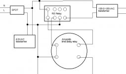
OK, see the attached diagram:
I'll stop by Radioshack and buy one. My basic understanding of the circuit then is this:
1. The wires from the switch side of the delay tube will go to the "trigger" (I don't know what to call them) connections on the relay.
2. The common connection on the RS relay will connect to mains L.
3. The normally open side of the RS relay will connect to the Hammond transformer. Hence when activated, the contacts will close and connect the transformer to mains L.
4. The normally closed side of the RS relay will connect to the Amperite...........
OK, see the attached diagram:
Attachments
- Status
- This old topic is closed. If you want to reopen this topic, contact a moderator using the "Report Post" button.
- Home
- Amplifiers
- Tubes / Valves
- switch snubber on preamp