Important with the big Russian '33 to Burn-In BEFORE attempting any matching....
To burn-in-
Run heaters Only for 24-48 hours.
heaters off, cool down for hour or so.
Then heaters On, only for half-hour.
Then arrange PSU of 60-80V etc, to pull 600mA with small neg on grid, to control current--monitor over first hour and trim G1 to maintain 600mA.
Leave for 2-3 hours drawing full current.--they get Bloody HOT!!-caution!
Kill B+ and then heaters, leave to cool completely and Then do your matching--BUT Remember, 6C33 Must be warmed up for around Half-hour with +B before taking any readings....
Time consuming process but pays out in life and less drift/stays matched issues....

Garter bias with low mu triodes is no fun. Big time energy waster...
I've done it and actually really, really like it. 165v supply, two 6AS7G in push-pull, and 330R cathode resistors each in a garter bias configuration. Works great, excellent balance, and sounds fantastic. Ignore the power consumption and excess heat. takes 33v or so each grid for full output, so 12AT7 or 6SL7 concertina works well, with headroom for negative feedback. This rig with 6SL7 up front is actually one of my favorite amplifier setups for low-moderate output uses, such as small bedroom rigs or similar. Efficiency be damned, as it sounds great and measures very respectably.
Only tricky part is getting 300~320v or so for the driver stage, which works fine with a dual ~115v secondary isolation transformer, just rectify each output and stack them on top of eachother. I've got a cheap isolation toroid that I simply added a set of 6 volt filament windings to, and it works great, and is cheap.
I could not agree more with most you said.I have designed and made P-P outputs using the 6C33C ...For both Class A and AB.... It is pretty straight forward....just a little bigger currents than usual.. Pretty descent tube.... As for toroids and saturating the cores... i wouldn't worry about it.. Depending on how you design the toroid it can tolerate imbalance... I usually don't use toroids for OPT's..for other reasons....Toroids choosen for OPT's are gapped cores and can deal with reasonable DC current imbalance without any problems.. If your worried about DC current matching....You can varry heater supply each valve to adjust the cuurent if reasonably close... Heater's are the worst offenders in modern day tubes...they have big variance... Some designers are anal and say you MUST run the tube at the ratted heater voltage...It's not that critical as long as you have adequet space charge density...if not then you may strip a cathode.... Whats more important is heater POWER...Lets say you drove constant current into a string of 10 6C33C valves....you will notice that the voltage drops across each will be different due to process variation...So whats correct??? Proper heater current?? or proper heater voltage??? I believe it's proper heater POWER..
Chris
Chris
But I would like to make people aware that some highly regarded toroidial PP OPTs that sport very high large signal inductances will brake down even under the smallest presence of dc-imbalance. The problem of dc imbalance under static conditions can be solved. But under low frequency dynamic conditions dc-current is part of the distortion that is practically unavoidable and a gap will still be needed. Ideally you want the gap optimized to cope with all this the best possible way. Otherwise, not only the inductance will more or less break down, but also additional low frequency distortion and intermodulation products will result.
Last edited:
Has anyone yet built a 6c33c push pull?
I ask because I recently bought what was listed as a full kit on eBay only to find it wasn’t and will certainly need the help of you guys to decode the part instructions (which don’t match the kit but do match the pcbs. This is a link to the ‘kit’ bought..
High-End 6C33C 2x100 Watt Stereo Triode Push-Pull Röhrenverstärker, Tube Amp.KIT | eBay
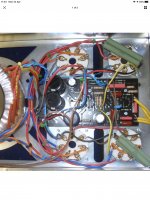
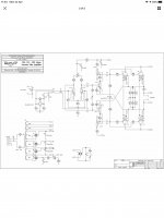
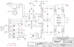
The photo and schematics appear to show the original configuration of using 4 6c33c’s per pcb driver. However I’m to understand that the Hartung was OTL.
Attachments
I understand your problem better!
it looks like the kit you bought was either
mixed is incomplete.
what is on the diagram:
otl with 4 6c33c and 3 ecc83 by side
what you bought is
pp opt with two 6c33c and 3 ecc83 per side
it does not seem to match the kit Hartung ps125 but has something else.
do a search with: Hartung OTL 30 II
you should find your answers
Very similar. I was only told that the kit wasn’t complete after I’d paid for it all. Once it arrived it became apparent that this was more a box of bits than a full kit.
Seller sent the schematics after a few back and forth emails. He was selling more of these kits using same pictures... all apparently incomplete. Even though sold as complete kit.
I only kept the stuff due to paying £270 which considering the iron and tubes and caps etc I didn’t think was a bad price. He listed the other kits at over £700 starting price after that.
I’ll make up a full list of components and their values tonight and ‘hopefully’ with as much help as I can get from you guys I might be able to make something of this..
Thanks for your input..
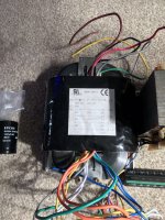
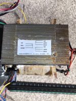
I do not know if your transformers are opt or power transform but according to the photos, they are more surely power transformer.
the same for the one at the center (the R-core), it looks more like a power transformer.
I think you have the principal in what you bought.
there must not be much difference in the 30w and the 60w anyway.
you have the power transformer
the tubes of powers
the signal / driver tubes
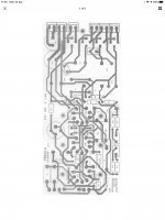
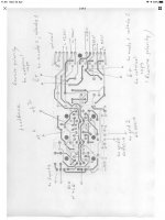
pcb
the same for the one at the center (the R-core), it looks more like a power transformer.
I think you have the principal in what you bought.
there must not be much difference in the 30w and the 60w anyway.
you have the power transformer
the tubes of powers
the signal / driver tubes
pcb
Doesn't look so bad for a cyclotron ")
They aren't ECC83 but ECC81. Max Vfk for those tubes is 90V, so best raise the heaters to around +50V.
And i think better decoupling the top anodes of the SRPP to ground (10µF/400V).
The power transformer voltages on the print drawing are lower (more reasonable) then in the schematic.
Here the schematic with the voltages/currents i expect you to find.
Mona
Attachments
- Status
- This old topic is closed. If you want to reopen this topic, contact a moderator using the "Report Post" button.
- Home
- Amplifiers
- Tubes / Valves
- 6C33B-C push pull with output transformer